CHECKING FOR CONTINUITY
••
Warning
••
To avoid possible damage to the meter or other equipment, turn off the power
source and discharge all high-voltage capacitors.
(1) Turn the rotary switch to the
position and press the
FUNC
button until
the
icon appears in the upper right corner of the LCD.
(2) Plug the black test lead into the
COM
jack and the red test lead into the
jack.
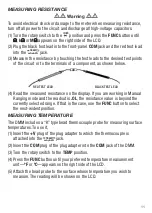
(3) Touch the test leads to any two points of the circuit. The resistance between
those two points will be displayed. If the resistance is <50
Ω
, the beeper will
sound continuously. If there is no continuity (an open circuit or a resistance
>50
Ω
) between the two points,
OL.
will appear on the readout.
CHECKING THE INTEGRITY OF A DIODE
••
Warning
••
To avoid possible damage to the meter or other equipment, turn off the power
source and discharge all high-voltage capacitors.
(1) Turn the function switch to the
position and press the
FUNC
button until
the
icon appears in the upper right corner of the LCD.
(2) Plug the black test lead into the front-panel
COM
jack and the red test lead
into the
jack.
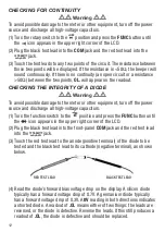
(3) Touch the red test lead to the anode (positive terminal) of the diode to be
tested and the black test lead to its cathode (negative terminal), as shown
below.
(4) Read the diode’s forward bias voltage drop on the display. A silicon diode
typically has a forward voltage drop of 0.7V. A germanium diode typically
has a forward voltage drop of 0.3V. A
0V
reading in both directions indicates
a shorted diode. A readout of
.OL
means either of two things: the leads are
reversed, or the diode is defective. Reverse the leads. If this still produces a
readout of
.OL
, the diode is defective and should be replaced.
TEMP
mAµAV
Ω
Ω
TEMP
mAµAV
Ω
Ω
12
RED TEST LEAD
BLACK TEST LEAD


