background image

Part list 

NO. 

NAME 

DESCRIPTION 

QTY 

1


Main frame 

1


2


Front stabilizer


1


3


Rear stabilizer


1


4


Saddle post 

1


5


Saddle 

1


6


Upper Upright post


1


7


Handlebars 

1


8


Console 

1


9


Console communication wire 

1


10


Motor communication wire 

1


11


Handle pulse connection wire 

2


12


Console outset 

2


13


Upright post cover 

1


14


Arm cover left 

1


15


Arm cover right 

1


16


Saddle cover(L) 

1


17


Saddle cover(R) 

1


18


Pedal(L) 

1


19


Pedal(R) 

1


20


Bottle holder 

1


21


handle knob 

1


22


Handlebar clamp ring 

1


23


Handlebar rotary knob 

Φ60×31×M10×20 

1


24


Philips C.K.S. full thread screw 

M5×10 

4


25


Bushing tube 

Φ10.5×Φ14×10 

1


26


Allen C.K.S. half thread screw 

M10×60×25 

4


27


Spring washer 

Φ10 

9


28


Curved washer 

Φ10.5×R100×t2.0 

10


29


Philips pan head full thread screw 

M4×6 

6


30


Allen C.K.S. full thread screw 

M8×20 

4


31


Spring washer 

Φ8 

4


Summary of Contents for BRX 300

Page 1: ...Ed Rev INSTRUCTION 02 20 GRLDTOORXBRX300E 00 iConsole App Manual www toorx it iconsole...

Page 2: ...y of your unit gather the necessary tools Having all of the equipment at hand will save time and make the assembly quick and hassle free NO NAME SPECIFICATION QUANTITTY 26 Allen C K S half thread scre...

Page 3: ...is fully assembled make sure there is a comfortable amount of free area around the unit for unobstructed operation NOTE Each step number in the assembly instructions tells you what you will be doing...

Page 4: ...WE RESERVE THE RIGHT TO AMEND THE PRODUCT WITHOUT PRIOR NOTICE DIMENSION Unfold 1090x560x1490mm SPEED RATIO 8 UP DOWN 9 levels 270mm distance FRONT BACK 70mm distance Console Handle bar Bottle Bolt Se...

Page 5: ...asher 27 and Allen C K S half thread screw 26 Step 2 Attach the rear stabilizer 3 to the main frame 1 with curved washer 28 spring washer 27 and Allen C K S half thread screw 26 Step 3 Loosen the knob...

Page 6: ...ranslate saddles 5 to proper position Then attach saddle decoration cover L 16 and saddle decoration cover R 17 to saddle post 4 with Philips C K S pan head full thread screw 29 3 Tighten the handle k...

Page 7: ...urved washer 28 and Hex locking nut 33 4 Attach upright post cover 13 and Upright post trim strip 46 to the main frame 1 Tip After connecting the communication line it is necessary to plug the communi...

Page 8: ...e 8 to upper upright post 6 with Philips C K S full thread screw 24 3 Through handle bar cover left 14 and handle bar cover right 15 out of the handlebar 7 Then attach them to upper upright post 6 wit...

Page 9: ...st the resistance of magnet control according to user 2 Since the machine with double flywheels and it will have huge moment of inertia when the user stop before high speed the user should minimize th...

Page 10: ...Exploded Drawing for assembly...

Page 11: ...cover 1 14 Arm cover left 1 15 Arm cover right 1 16 Saddle cover L 1 17 Saddle cover R 1 18 Pedal L 1 19 Pedal R 1 20 Bottle holder 1 21 handle knob 1 22 Handlebar clamp ring 1 23 Handlebar rotary kno...

Page 12: ...ew ST4 12 8 45 Hexagon socket head full tooth screw M6 15 4 46 Upright post trim strip 1 47 End cap 4 48 Feet pad 4 49 Hexagon socket large flat head hollow screw 8 33 M6 15 2 50 Wheels 55 25 8 2 51 A...

Page 13: ...rew M10 38 1 70 Hex nut M10 4 71 Philips C K S self tapping screw ST4 16 8 72 Power communication wire 1 73 Magnetic sensor 1 74 Cover L 1 75 Cover R 1 76 Foam grip 26 t3 0 600 2 77 Square pipe plug 2...

Page 14: ...Half drawing for assembly 20 37 26 3 1 2 27 29 29 16 37 18 19 27 28 14 15 6 13 17 4 28 26 21 7 11 12 24 8 9 22 5 46 25 23 9 10 28 27 34 27 35 34 27 35 28 27 35 36 28 33 28 35...

Page 15: ...1 17 Saddle cover R 1 18 Pedal L 1 19 Pedal R 1 20 Bottle holder 1 21 handle knob 1 22 Handlebar clamp ring 1 23 Handlebar rotary knob 60 31 M10 20 1 24 Philips C K S full thread screw M5 10 4 25 Bus...

Page 16: ...99 99 CALORIES Burned calories during workout display Range 0 9999 PULSE Pulse bpm displayed during exercise Pulse alarm when over preset target pulse RPM Rotation per minute Range 0 999 WATT Workout...

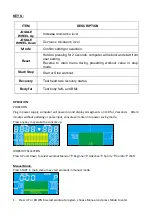
Page 17: ...al Mode Press START in main menu may start workout in manual mode 1 Press UP or DOWN to select workout program choose Manual and press Mode to enter ITEM DESCRIPTION JOGGLE WHEEL Up Increase resistanc...

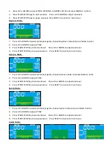
Page 18: ...ss START STOP key to pause workout Press RESET to reverse to main menu Advance Mode 1 Press UP or DOWN to select workout program choose Advance mode and press Mode to enter 2 Press UP or DOWN to prese...

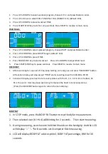
Page 19: ...n menu RECOVERY 1 After exercising for a period of time keep holding on hand grips and press RECOVERY button All function display will stop except TIME starts counting down from 00 60 to 00 00 2 Scree...

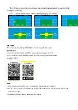
Page 20: ...y iConsole APP Turn on Bluetooth on tablet search for console device and press connect Turn on iconsole app on tablet and press connect to start workout with tablet password 0000 NOTE 1 Once console i...

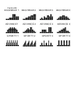
Page 21: ...BEGINNER 1 BEGINNER 2 BEGINNER 3 BEGINNER 4 ADVANCE1 ADVANCE 2 ADVANCE 3 ADVANCE 4 SPORTY 1 SPORTY 2 SPORTY 3 SPORTY 4 Program profile...

Page 22: ...GARLANDO SPA Via Regione Piemonte 32 Zona Industriale D1 15068 Pozzolo Formigaro AL Italy www toorx it info toorx it...

Reviews: