background image


8

ASSEMBLY INSTRUCTION 

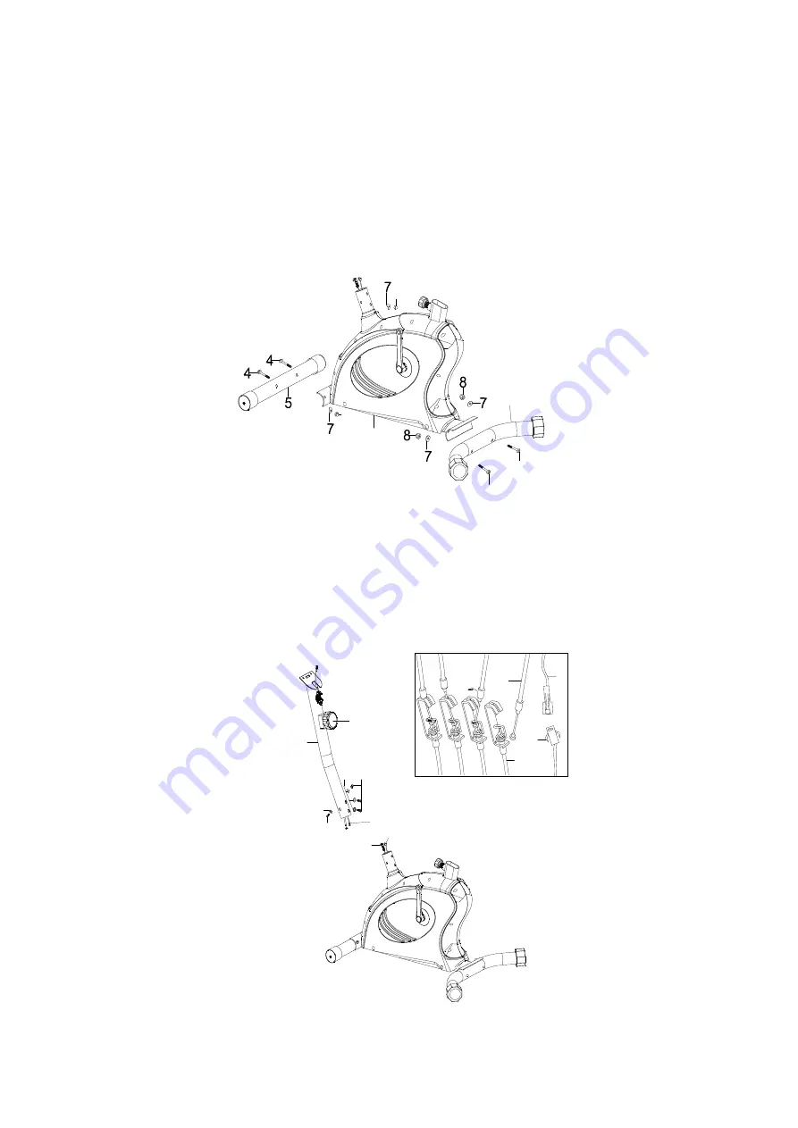
STEP 1 

(a) Attach front stabilizer (5) to main frame (1), tighten with 2 sets of carriage bolt (4), curve 

washer (7) and domed nut (8). 

(b) Then, attach rear stabilizer (2) to main frame (1), tighten with 2 sets of carriage bolt (4), 

curve washer (7) and domed nut (8). 


STEP 2


(a) Take front post (12) and connect middle sensor wire (14) with lower sensor wire (65).   

(b) Adjust the tension control knob (13) to level 8, then connect it with the lower tension cable 

(32). Insert front post (12) into main frame (1) and tighten with 4 sets of allen screw (10) 

and curve washer (7).   


8

8

1

2

4

4

13

10

7

10

7

32

13

12

14

32

65

14

65

Summary of Contents for BRX60

Page 1: ...Ed 02 17 Rev 00 INSTRUCTION...

Page 2: ...PER 1 46 FRENCH NUT 4 14 SENSOR WIRE MIDDLE 1 47 PULLY 1 15 SCREW M5 10 2 48 END CAP FOR CRANK 2 16 SPACER 1 49 SPACER FOR MAGNET 2 17 SQUARE WASHER 1 50 MAGNETIC ASSEMBLY 1 18 COMPUTER 1 51 HEX HEAD...

Page 3: ...4 EXPLODED DIAGRAM 2 3 4 4 4 4 5 6 6 1 7 8 7 7 7 8 8 8 9 10 35 35 12 13 14 15 10 19 20 21 22 23 25 24 27 24 25 26 27 11 32 33 34R 34L 36 36 37 28 30 31 29 64 16 17 62 61 41L 3 65 18...

Page 4: ...5 43 39 40 47 42 22 31 29 29 39 39 39 40 40 44 45 51 50 49 49 53 55 56 57L 57R 58 58 59 60 38 46 46 52 54 63 41L 41R 46 46 48 48...

Page 5: ...4 8 Domed Nut M10 4 10 Allen Bolt M8 16 4 23 T type Knob 1 33 Clamp cover 1 35 Curve Washer 8 20 4 Allen Key 6mm 1 Box Wrench 1 Above described parts are all the parts you need to assemble this machin...

Page 6: ...ION Q TY 1 Main Frame 1 2 Rear Stabilizer 1 5 Front Stabilizer 1 11 Seat 1 12 Front Post 1 18 Computer 1 19 Handlebar 1 28 Seat Post 1 34 Left Right Pedal 1 1 User Manual 1 Hardware bag 1 NO 1 NO 5 NO...

Page 7: ...en with 2 sets of carriage bolt 4 curve washer 7 and domed nut 8 STEP 2 a Take front post 12 and connect middle sensor wire 14 with lower sensor wire 65 b Adjust the tension control knob 13 to level 8...

Page 8: ...n the wire holder on the Lower Tension Connector Pull the Upper Tension Connector backward and slide the wire through the slot on the bracket Drop down the Connector so the fitting sits firmly on top...

Page 9: ...the front post and insert end cap for wire 37 into the front post c Connect the hand pulse wires 20 and middle sensor wire 14 to the back of the computer 18 Attach the computer onto the bracket of fr...

Page 10: ...hem to their appropriate crank arm 41 The right pedal is on the right hand side of the cycle as you sit on it Note that the right pedal should be threaded on clockwise and the left pedal on counter cl...

Page 11: ...when setting 2 Press the button and hold for 2 seconds to reset all value except Odometer to be zero When the user replace batteries all the values will reset to ZERO automatically FUNCTIONS OPERATION...

Page 12: ...s in the battery case on the back of monitor Whenever batteries are removed all of the functions values will be reset to zero 3 The batteries must be removed from the appliance before it is scrapped a...

Page 13: ...GARLANDO SPA Via Regione Piemonte 32 Zona Industriale D1 15068 Pozzolo Formigaro AL Italy www toorx it info toorx it...

Reviews: