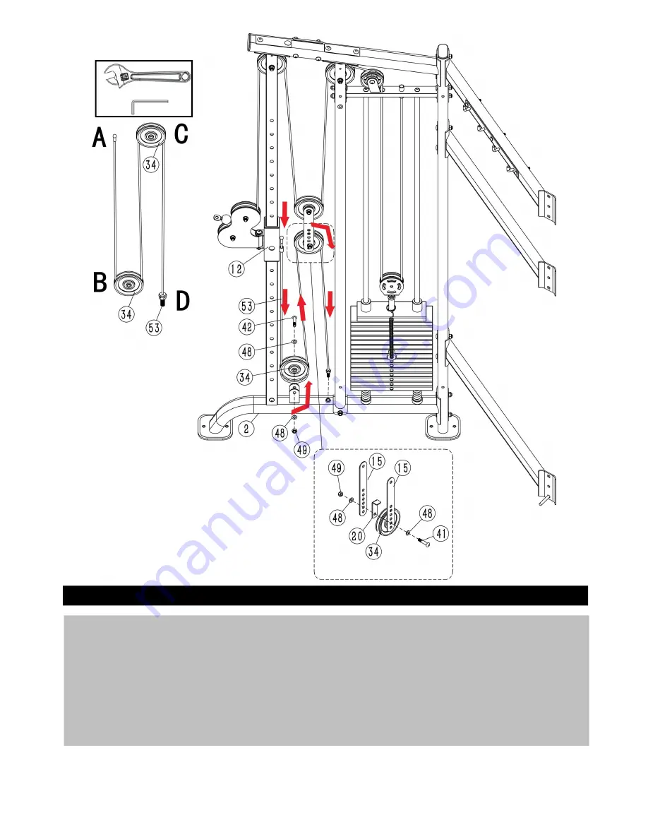
Step 13
1. Put the End
A
of the Adjustment Cable (
53
) through the sleeve on the right side of the Right Sliding
Frame (
12
) as shown in the diagram, then screw the End
D
in the nut on the Base Frame (
2
).
2. Connect the Pulley φ114
B
(
34
) and Adjustment Cable (
53
) to the Base Frame (
2
) using 1 x
M10×45mm Allen Bolt (
42
), 2 x ø10mm Washers (
48
) and 1 x M10 Aircraft Nut (
49
), and ensure the
cable in the pulley groove.
3. Connect the Pulley φ114
C
(
34
) and Adjustment Cable (
53
) to 1 x L- Shaped Cable Protector (
20
) and
2 x Double Pulley Bracket (
15
) using 1 x M10×50mm Allen Bolt (
41
), 2 x ø10mm Washers (
48
) and 1 x
M10 Aircraft Nut (
49
).
4. Cable tension can be adjusted by the End
D
of the Adjustment Cable (
53
).
20
Summary of Contents for CSX3000
Page 1: ...Ed 10 18 Rev 00 INSTRUCTION...
Page 2: ...Components Fixings 3...
Page 3: ...Components Parts 1 4...
Page 4: ...Components Parts 2 5...
Page 5: ...Components Parts 3 6...
Page 12: ...Step 6 Repeat Step 5 to assemble the left weight stack 13...
Page 18: ...Step 12 Repeat the step 11 to assemble the left Upper Cable 52 19...
Page 20: ...Step 14 Repeat step 13 to assemble the left Adjustment Cable 53 21...
Page 26: ...40 M10 65mm Allen Bolt 2 8 Allen Wrench 1 41 M10 50mm Allen Bolt 4 26...


