background image


After power on, user may press START/STOP button to start exercise in MANUAL immediately 
without any setting. 
Level can be adjusted during exercise by press UP or DOWN. 

5.


PROGRAM


      Before exercise in Program mode, user may set up TIME target. 

Press UP and DOWN to select Program with 12 profiles and press ENTER/MODE to confirm. 
Level can be adjusted during exercise by press UP or DOWN. 

6.


H.R.C.


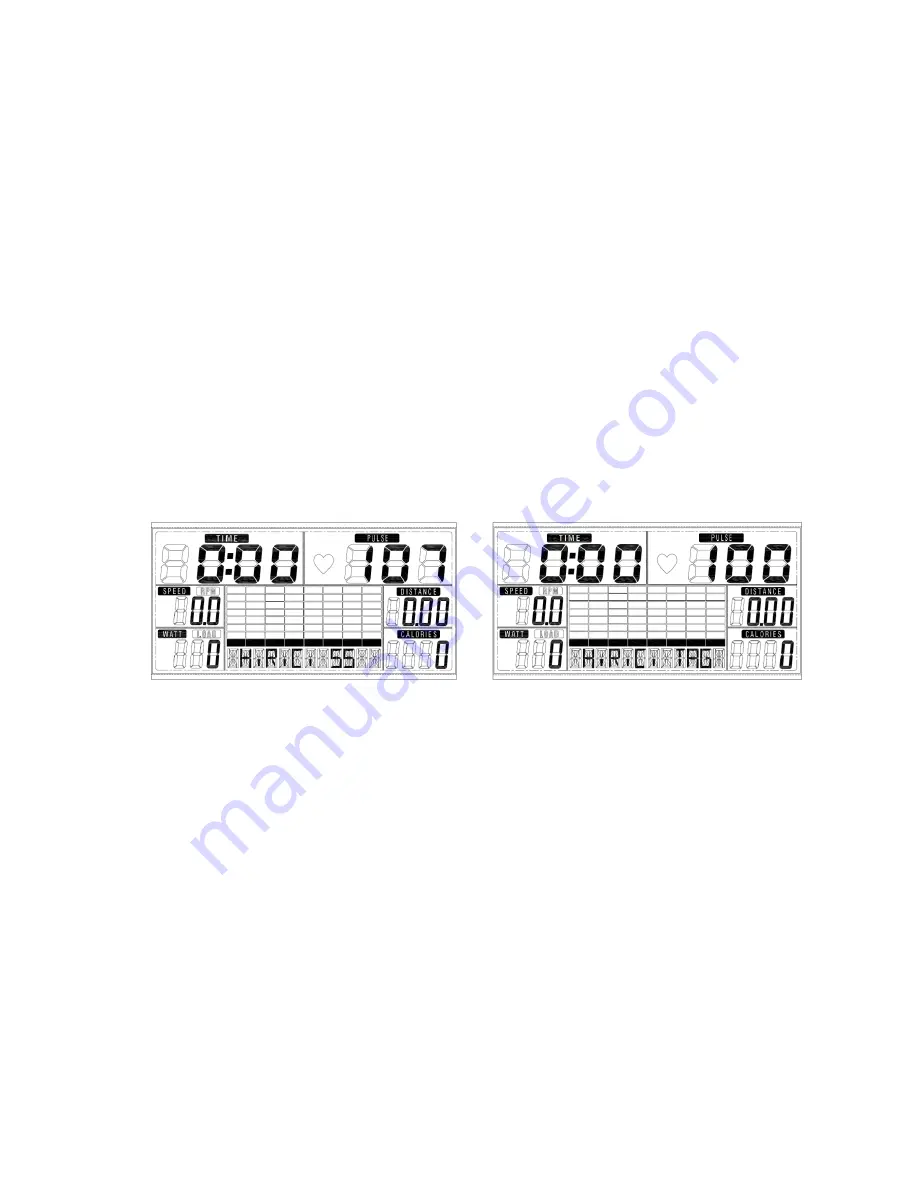
Select the H.R.C. mode and press the MODE key to enter into the setting mode. AGE 
default value is 25 (years old). There will be 4 selections: H.R.C55, H.R.C.75, H.R.C.90 
and H.R.C. TAG; use the UP/ DOWN key to select one program and press the MODE 
key after selection is determined (FIGURE G & H). User’s selection and a sign of “55%” 
will be displayed in the PULSE column according to the AGE user inserted. If user selects 
H.R.C. TAG (press the MODE key to enter), preset PULSE value “100” will be shown in 
flashing text and user can press the UP/ DOWN key to adjust target range from 30~230. 


                      G                                                                            H 


7.


USER PROGRAM


      User may press UP, DOWN and then press MODE to create his own profile. (from column 1 to 

column 20) User may hold on pressing MODE button for 2 seconds to quit profile setting. 

8.


WATT : 

The preset watt value 120 is flashing on screen in WATT setting mode.    User may use UP, 
DOWN button to set target value from 10 to 350.    Press MODE button for confirm. 

9.


BODY FAT: 

9-1 In STOP mode, press the BODY FAT button to start body fat measurement. 
9-2 Then selected user (U1~U4) will blinking for 2 seconds.    Then start measuring. 
9-3 During measuring, user have to hold both hands on the handgrip. And the LCD will display “-

-” “--“ for 8 seconds until computer finish measuring.     

9-4 LCD will display BODY FAT advice symbol, BODY FAT percentage, BMI for 30 seconds. 

Summary of Contents for ERX100

Page 1: ...Edizione Revisione 00 INSTRUCTION 08 16 00...

Page 2: ...f fun and success during training Please note and follow the enclosed safety and assembly instructions carefully If you have questions please do not hesitate to contact us Table of Content as below 1...

Page 3: ...EXPLODED DRAWING 111 110 112...

Page 4: ...19 1 5T 8 14L Plastic cover Left 1 14R Plastic cover Right 1 15 Screw M5 12 7 16 Upper computer cable 1 17 Screw M5 12mm 4 18 Self tapping screw M4 15 5 19L 1 Plastic cover for left handlebar 1 19L 2...

Page 5: ...cable 1 42 Front plastic cover 1 43 Lower computer cable 1 44 Washer 8 19 1 5T 4 45L Front end cap left 1 45R Front end cap Right 1 46 Front stabilizer 1 47 Allen screw M8 57 2 48L Pedal connecting t...

Page 6: ...M5 15 14 75 Joint lever for chain cover 2 76 Nut M10 1 25 2 77 Round cover 2 78 Crank 2 79 Washer 5 16 1 8 80 Self tapping screw 8 81 C shapped washer 1 82 Curved washer 1 83 Washer 2 84 Bearing 6004...

Page 7: ...22 1 5T 1 101 Nut M6 1 102 Headed screw M6 75 1 103 Spring 1 104 Hex nut 2 105 C shaped washer 1 106 Bearing 1 107 Flywheel 6300RS 1 108 Flywheel axle 10 110MM 1 109 Bearing 6000RS 1 110 Allen key wr...

Page 8: ...ASSEMBLY INSTRUCTION STEP 1 1 Fasten the Front stabilizer 46 with 2 x M8 x 57 Allen bolts 47 2 Fasten the Rear stabilizer 94 with 2 x M8 x20 Flat head inner hexagon screws 88 STEP 2...

Page 9: ...onto the Plastic cover 42 2 Connect the Upper computer cable 16 and the Lower computer cable 43 3 Then place the Handlebar post 24 onto the Main frame 58 and fix it using 8 M8 20mm Allen bolts 11 8 M...

Page 10: ...ion rod and secure it using 19 5 38 0 5mm Flat washer 21 Screw caps 29 Spring washer 12 and M8x20mm Anti loose Allen bolt 30 for each side 3 Put the Upper handlebar 3L R onto the Lower handlebar 27 an...

Page 11: ...m Self tapping screw 18 and 4 x Screw M5x15 33 2 Attach the Left footplate bar 48L onto the Left crank and secure it with 8x21x2T Washer 68 8 Spring washer 12 and M8x20 Anti loose Allen bolt 69 Put th...

Page 12: ...Tube spacer 25 T shape knob 26 tightly 2 Taking the Computer 1 and remove the 4 pre fitted Screws 17 in the back of the computer Now connect the Upper computer cable 16 with the Computer and the Hand...

Page 13: ...Assemble the Plastic cover 19L 1 and 19L 2 on the handlebar 27 with the screw 18 and the screw 20 do the same to the right plastic 19R 1 and 19R 2 Now your machine is ready for us...

Page 14: ...s UP To select training mode and adjust function value up DOWN To select training mode and adjust function value down BODY FAT For body fat measurement DISPLAY EXERCISE DATA TIME Display range 0 00 99...

Page 15: ...eight and weight for U1 U4 drawing B C 2 After user data set up computer will display main menu drawing D A B C D 3 In main menu first exercise program MANUAL will flash user may press UP and DOWN but...

Page 16: ...ding to the AGE user inserted If user selects H R C TAG press the MODE key to enter preset PULSE value 100 will be shown in flashing text and user can press the UP DOWN key to adjust target range from...

Page 17: ...F1 F2 to F6 F1 is the best F6 F6 is the worst User may keep exercising to improve the heart rate recovery status Press the RECOVERY button again to return the main display NOTE 1 This computer requir...

Page 18: ...GARLANDO SPA Via Regione Piemonte 32 Zona Industriale D1 15068 Pozzolo Formigaro AL Italy www toorx it info toorx it...

Reviews: