background image


P

P

A

A

R

R

T

T

S

S


L

L

I

I

S

S

T

T 


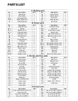
A. Welding parts


No. 

Description 

QTY 


No. 

Description 

QTY 

A1 

Main frame 

A5 

Incline Frame 

A2 

Base frame 

A6 

滤波器支撑座 

A3L 

Left upright tube 

A7 

跑板加强管 

A3R 

Right upright tube 

A11 

Motor Barcket 

A4 

Handrail bracket 

A13 

Belt Guide 

B. Plastic parts


No. 

Description 

QTY 


No. 

Description 

QTY 

B1 

Computer chip 

B17 

Transport wheel 

B1-1 

Overlay 

B1

Silicon oil 

B1-2 

Membrane key 

B20 

Protecting wire plug 

B1-3 

Computer panel 

B21 

Square plug 

B2 

Computer cover 

B22 

Left motor side cover 

B3 

Handrail foam 

B23 

Right motor side cover 

B4 

Plug 

B26 

Cushion 

B6 

Transport wheel 

B27 

New cushion 

B8 

Flat pad 

B31 

Rubber pad 

B9 

Horseshoe pads 

B41L 

Left speaker bottom cover 

B11L 

Left side cover 

B41R 

Left speaker bottom cover 

B11R 

Right side cover 

B42 

Handrail plug 

B13 

Motor cover 

B43 

PVC Buffer 

B15 

Side rails 

B44 

EVA pad 

B16L 

Left end cap 

B77 

EVA pad 

B16R 

Right end cap 

B80 

Motor decoration cover 

C. Electric and drive parts 

No. 

Description 

QTY 


No. 

Description 

QTY 

C2 

Running belt 

C19 

MP3 Line 

C3 

Rear roller 

C20 

Magnetic ring 

C4 

Front roller 

C21 

Inductance 

C5 

Running board 

C22 

Filter 

C6 

Cylinder 


C23 

Overload protector 

C7 

Motor belt 

C25 

AC motor 

C8 

Power switch 

C26 

Inverter (AC controller) 

C10 

Left short keys 

C27 

Single cord (Black 300) 

C11 

Right short keys 

C31 

Single cord (Red 150) 

C12 

Incline Motor 

C32 

Single cord (Black 150) 

C13 

Safety key 

C33 

Grounding cable 

C14 

Single cord (Red 300) 

C34 

Outlet 

C15 

Power cable 

C35 

Single cord

CE 

set

) 

C16 

Upper cable 

C37 

Chest belt 

C17 

Lower cable 


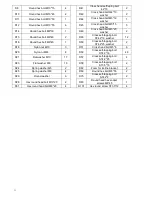
D. Hardware parts


No. 

Description 

QTY 


No. 

Description 

QTY 

D1 

Cross head with allen wrench T6 

D33 

Hex round head bolt M8*55 

D2 

Allen wrench T6 

D34 

Hex round head bolt M8*60 

D4 

Round hex bolt M10*65 

D36 

Cross head bolt M6*25 

D6 

Round hex bolt M8*50 

D39 

Cross head bolt M6*40 

20 

Summary of Contents for TRX 100

Page 1: ...Ed 03 17 Rev 00 INSTRUCTION APP READY ...

Page 2: ...CTIONS 4 FOLDING UNFOLDING INSTRUCTIONS 7 INCLINE INSTRUCTIONS 8 GROUNDING METHODS 9 OPERATION GUIDE 10 GETTING STARTED GUIDE 15 SAFETY EXERCISES 16 WARM UP EXERCISES 17 MAINTENANCE INSTRUCTIONS 18 BELT ADJUSTMENT 19 EXPLODED DRAWING 20 PARTS LIST 21 ERROR CODE AND SIGNIFICANCE 23 ...

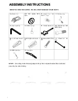
Page 3: ... hex bolt M10 15 4pcs C13 Safety key 1pc D3 Allen wrench 1pc B18 Silicon oil 1pc D1 Screw driver 1 pc D12 Round hex bolt M8 55 4pcs B11L Left side cover 1 pc B11R Right side cover 1 pc D48 Screw ST4 2 19 2 pcs C15 Power co de 1pc C19 MP3 Line 1pc C37 Chest belt STEP 1 According to the following steps to lift up the computer bracket Be careful not press the line when folding ...

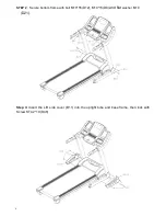
Page 4: ...4 STEP 2 Secure bottom frame with bolt M10 55 D12 M10 15 D8 and flat washer M10 D21 Step 3 Insert the L R side cover B11 into the upright tube and base frame then lock with Screw ST4 2 19 D48 ...

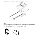
Page 5: ...P3 line C19 and Power code C15 Step 5 Plug in Bluetooth dual kit Warning voltage of dual kit is 3 3V and cannot plug into computer lapto p or it will be damaged 1 Take out the Bluetooth kit and push the cover down to let USB slot appears ...

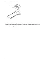
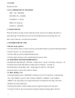
Page 6: ...on treadmill Bluetooth ATTENTION Must confirm complete assembly as the required above and lock all bolts Do the following operations after checking everything is OK Before you use the treadmill please read the instructions carefully ...

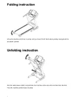
Page 7: ... to pull up until you heard click that made by safety casing stuck the pneumatic cylinder U Un nf fo ol ld di in ng g i in ns st tr ru uc ct ti io on n Kick the safety sleeve lightly and pull down the machine at the same time as the arrow direction Then the machine will fall down smoothly ...

Page 8: ...cordance with all local codes and ordinances DANGER Improper connection of the equipment grounding conductor can result in a risk of electric shock Check with a qualified electrician or serviceman if you are in doubt as to whether the product is properly grounded Do not modify the plug provided with the product if it will not fit the outlet Please find a proper outlet installed by a qualified elec...

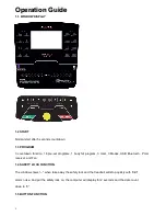
Page 9: ...ction 16 pre set programs 1 body fat program 3 User 3 Modes USB Bluetooth Polar receiver and Fan 1 4 SAFETY LOCK FUNCTION The window shows when take away the safety lock and the treadmill will stop quickly with didi alarm noise And put the safety lock on the computer will display for 2 seconds and the date count down to 0 1 5 BUTTON FUNCTION ...

Page 10: ...d H 2 is the distance countdown mode H 3 is the calorie countdown mode press the SPEED button to adjust the data After that press the START button to start this treadmill 1 5 4 SPEED BUTTON SPEED Adjust speed when treadmill start the increment is 0 1km time in kilometer Press the button more than 2 seconds and it will be up or down automatically 1 5 5 SPEED QUICK BUTTON Press the speed quick butto...

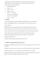
Page 11: ...ess quick speed key you can quickly adjust the speed you want 1 10 COUNTDOWN FUNCTION PARAMETER DATA Countdown time initial setting 30 00 minutes setting range 5 00 99 00 minutes each step 1 00 Countdown calorie initial setting 50therm setting range 10 990 term each step 10 Countdown distance initial setting 1 0km setting range 0 5 99 9 km each step 0 1 Cycle switch order is manual time distance c...

Page 12: ...you just can set one of them at one time press last item to set running the setting parameter is countdown others display normal data 1 13 4 On display Distance covered Calories burnt Pulse reading Body Fat test shown is only for indicative purpose and may vary from machine to machine Do not compare these readings to a medical instrument 1 13 5 Speed control acceleration at 0 5km s deceleration at...

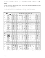
Page 13: ... 6 4 2 INCLINE 0 2 4 6 4 2 1 0 1 1 2 2 2 2 3 0 P6 SPEED 2 4 5 5 6 6 8 8 6 6 8 8 6 9 6 2 INCLINE 0 1 3 4 4 3 3 1 2 1 2 1 2 1 2 0 P7 SPEED 2 7 7 9 9 4 4 12 12 4 4 8 8 4 4 2 INCLINE 0 1 1 2 2 3 3 4 4 3 3 2 2 1 1 0 P8 SPEED 2 2 6 6 6 8 9 10 11 12 9 5 5 5 3 2 INCLINE 0 1 2 4 2 1 2 4 2 1 2 4 2 1 2 0 P9 SPEED 2 4 8 10 2 4 8 10 2 4 10 2 4 10 4 2 INCLINE 0 1 2 3 4 5 6 7 8 9 8 6 4 2 1 0 P10 SPEED 2 5 6 7 8 ...

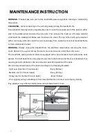
Page 14: ...r from underneath the belt WARNING Always unplug the treadmill from the electrical outlet before removing the motor cover At least once a year remove the motor cover and vacuum under the motor cover This treadmill s walking belt and deck are equipped with a pre lubricated low maintenance deck system The belt deck friction may play a major role in the function and life of your treadmill thus requir...

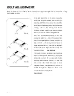
Page 15: ...Once the treadmill belt swerving to the left unplug the safety lock turn off the power then with the left adjusting bolt clockwise rotation 1 4 laps and turn on the safety lock and power to make treadmill running checking the deviation of the treadmill belt Repeat the above steps until the belt centered See picture B The treadmill belt will gradually relax after above steps or after a period of ti...

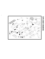
Page 16: ...E E X X P P L L O O D D E E D D D D R R A A W W I I N N G G 19 C37 D24 B43 D39 D23 B41R D36 B43 C20 B4 D21 D48 C11 B11L D21 B31 C32 C31 B13 D45 B80 B44 B6 B9 D21 D4 D21 D21 D21 D75 D1 ...

Page 17: ...uffer 2 B15 Side rails 2 B44 EVA pad 1 B16L Left end cap 1 B77 EVA pad 4 B16R Right end cap 1 B80 Motor decoration cover 1 C Electric and drive parts No Description QTY No Description QTY C2 Running belt 1 C19 MP3 Line 1 C3 Rear roller 1 C20 Magnetic ring 1 C4 Front roller 1 C21 Inductance 1 C5 Running board 1 C22 Filter 1 C6 Cylinder 1 C23 Overload protector 1 C7 Motor belt 1 C25 AC motor 1 C8 Po...

Page 18: ...Round hex bolt M8 45 1 D50 Cross self tapping bolt ST4 2 25 washer 2 D18 Nylon nut M10 3 D51 Cross head bolt M5 8 6 D20 Nylon nut M8 8 D52 Cross self tapping bolt ST4 2 16 46 D21 Flat washer M10 17 D57 Cross self tapping bolt ST4 2 25 4 D23 Flat washer M8 19 D58 Cross self tapping bolt ST3 5 16 2 D24 Spring washer M5 2 D62 Foam for incline bracket 2 D25 Spring washer M8 4 D69 Round hex bolt M8 55 ...

Page 19: ...GARLANDO SPA Via Regione Piemonte 32 Zona Industriale D1 15068 Pozzolo Formigaro AL Italy www toorx it info toorx it ...

Reviews: