background image


21


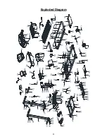
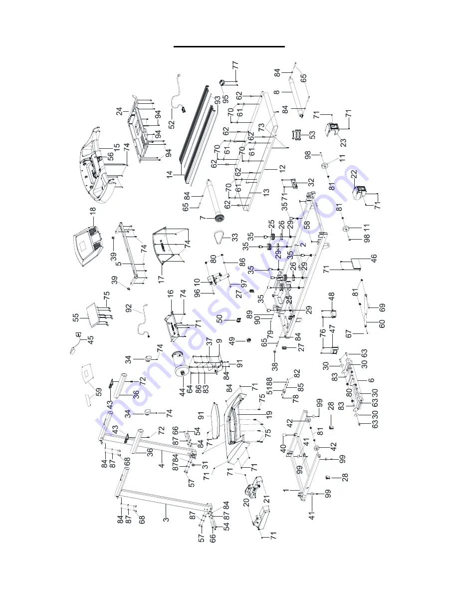
Exploded Diagram


Summary of Contents for TRX 50 S EVO

Page 1: ...Ed 03 17 Rev 00 INSTRUCTION ...

Page 2: ...y1 Multi Wrench Qty1 6 Allen Wrench Qty1 54 M8 Á 90mm Allen Bolt Qty4 71 ST4 8 Á 15mm Philip Screw w washer Qty2 66 M8 Á 80mm Allen Bolt Qty2 57 M8 Á 15mm Allen Bolt Qty4 20 Left Mast Cover Lubricating Oil 21 Right Mast Cover 45 Safety Key 3 Left Console Mast 4 Right Console Mast Main Frame Hardware pack Console 52 Power cord ...

Page 3: ...Pack Contents 68 20mm Allen Bolt 4 71 87 66 84 8mm Washer 14 80mm Allen Bolt 2 8mm Spring Washer 14 15mm Phillips Screw 2 5 Allen Wrench 1 6 Allen Wrench 1 Multi Wrench 1 54 90mm Allen Bolt 4 15mm Allen Bolt 4 57 ...

Page 4: ...5 Product Overview Pulse Sensor Console Mast Cover Transport Wheel Handle Grip Safety Key Console Mast Motor Cover Side Rail End Cap Running Deck ...

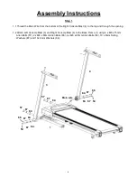
Page 5: ...and through the opening 1 2 Attach Left Console Mast 3 and Right Console Mast 4 to the Base Frame 1 using 4 x M8 x 15mm Allen Bolts 57 2 x M8 x 80mm Allen Bolts 66 4 x M8 x 90mm Allen Bolts 54 10 x 8mm Spring Washers 87 and 10x 8mm Washers 84 3 1 4 54 84 87 66 87 84 84 87 54 66 87 84 Main wire 87 87 57 57 84 84 ...

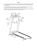
Page 6: ...m the Right Console Mast 4 2 2 Insert the connected wires into the handles of the Left Console Mast 3 and Right Console Mast 4 to ensure they don t get pinched between the console and frame of the treadmill 2 3 Attach the console to the Left Console Mast 3 and Right Console Mast 4 using 4 x M8 x 20mm Allen Bolts 68 4 x 8mm Spring Washers 87 and 4 x 8mm Washers 84 Console B 3 4 A A B 68 84 87 84 87...

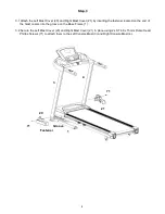
Page 7: ... located on the end of the mast covers into the groove on the Base Frame 1 3 2 Secure the Left Mast Cover 20 and Right Mast Cover 21 in place using 2 x ST4 8 x 15mm Dome Head Philips Screws 71 to attach them to the Left Console Mast 3 and Right Console Mast 4 20 3 21 4 Fastener Groove 1 71 71 ...

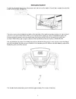
Page 8: ...e treadmill will power off Please unplug the power source and push down the button and then turn on the switch to restart your workout If the button pops up again please contact our National Service Centre on 1800 465 070 The treadmill will only work if the Safety Key 45 is attached to the groove in the console Insert the Safety Key 45 and attach the clip onto your clothes If it is necessary to tu...

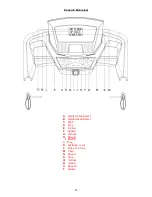
Page 9: ...Overview A Quick Incline Select B Quick Speed Select C Start D Stop E Incline F Speed G Incline H Speed I MODE J Prog K Distance or cal L Pulse or incline M Time N Speed O prog Q Incline R Incline S Speed T Speed ...

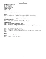
Page 10: ...s to select your desired running deck incline with 4 8 12 15 SPEED UP DOWN Press to increase decrease exercise speed by 0 1km h Press to select training time under program workout mode Press to choose the desired training target Time Distance Calorie under training target control workout mode INCLINE UP DOWN Press to increase decrease running deck incline by 1 Press to select training time under p...

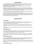
Page 11: ... MODE Turn on the treadmill and press Start button on the console Press Speed or Speed on the console or the handle to adjust the speed to the desired setting Pressing Speed or Speed buttons will increase decrease the speed by 0 1km h increments Press Incline or Incline button on the console of the handle to adjust the running deck incline to the desired setting Pressing Incline or Incline buttons...

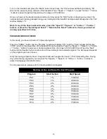
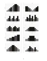
Page 12: ...et programs Press the PROG button and the Program window will display P01 and the Time window will display 30 00 which is the preset time of the treadmill for each program Press the Speed Speed or Incline Incline buttons to select your desired workout time the range is 5 00 to 99 00 min Press the Start button and the treadmill will count down from three and begin the selected program The start spe...

Page 13: ...14 ...

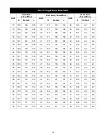
Page 14: ...km h During workout when your heart rate is lower than the preset value and the difference value is within 10 then the treadmill will increase the speed by 0 4Km h every ten seconds while the difference value is larger than 10 the treadmill will increase the speed by 0 8Km h every ten seconds until your target heart rate is achieved the speed can increase maximum to to 10Km h When your heart rate ...

Page 15: ... 93 93 22 188 119 119 44 167 106 106 66 146 92 92 23 187 118 118 45 166 105 105 67 145 92 92 24 186 118 118 46 165 104 104 68 144 91 91 25 185 117 117 47 164 103 103 69 143 91 91 26 184 116 116 48 163 103 103 70 143 90 90 27 183 116 116 49 162 103 103 71 142 90 89 28 182 115 115 50 162 102 102 72 141 90 89 29 181 115 115 51 161 101 101 73 140 90 88 30 181 114 114 52 160 101 101 74 139 90 88 31 180...

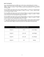
Page 16: ...y 170 which is the pre set user s body height in cm Press the Speed Speed or Incline Incline buttons to select your correct body height the range is 50 to 250cm Press the MODE button again and the Incline window will display F 4 and the Dis window will display 70 which is the pre set user s body weight in kg Press the Speed Speed or Incline Incline buttons to select your correct body weight the ra...

Page 17: ...sed To centre the running belt or adjust the tension of the running belt simply follow the instructions below Start the treadmill without anybody on the running belt press the Speed button until the speed reaches 6km h Observe whether the running belt is leaning toward the right or left side of the deck If it is towards the left side of the deck use 6 Allen Key 104 to turn the left adjustment bolt...

Page 18: ...to ensure an optimal operation of the treadmill After every 2 months of operation lift the side of the running belt and feel the underside surface of the belt as far as possible If traces of silicon lubricant are found further lubrication is not necessary In case of a dry surface refer to the instructions below Only use 100 silicon oil to lubricate your treadmill deck To apply lubricant on the bel...

Page 19: ...21 Exploded Diagram ...

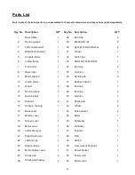
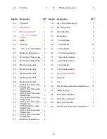
Page 20: ...roller 1 35 Cushion 8 9 Motor support 1 36 Handle grip 2 10 Incline motor 1 37 Rubber Cushion 1 11 Wheel 2 38 End cap 1 12 Running deck 1 39 End cap 2 13 Running belt 1 40 Cushion 1 14 Side rail 2 41 Shock pad 4 15 Console housing 1 42 Wheel 2 16 Back cover 1 43 Pulse sensor 2 17 Bottom cover 1 44 Motor 1 18 Screen cover 1 45 Safety key 1 19 Motor cover 1 46 Controller 1 20 Left mast cover 1 47 In...

Page 21: ...0mm Allen Bolt 4 89 Ф4mm Washer 1 66 M8 80mm Allen Bolt 2 90 Ф4mm Spring Washer 1 67 M8 30mm Allen Bolt 1 91 Motor cover decoration 1 68 M8 20mm Allen Bolt 4 92 Main wire 1 69 M8 45mm Allen Bolt 1 93 EVA 4 70 ST4 8 15mm Dome Head Philips Screw 8 94 ST4 8 12mm Dome Head Philips Screw 12 71 ST4 8 15mm Dome Head Philips Screw 18 95 Safety key plug 1 72 ST4 2 50mm Dome Head Philips Screw 2 96 M10 45mm...

Page 22: ...GARLANDO SPA Via Regione Piemonte 32 Zona Industriale D1 15068 Pozzolo Formigaro AL Italy www toorx it info toorx it ...

Reviews: