❏
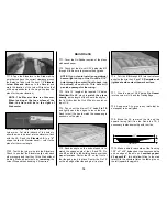
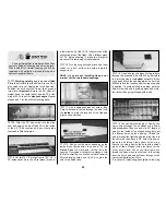
18. Tape the Elevators to the Stab making
sure that you have the correct clearance around
the Balance Tabs. Hold the bent 1/8”
Elevator
Joiner Wire and Horn
up to the Elevator and
mark the location of the Joiner Wire holes that
will be perpendicular to the hinge line (see the
plans for the joiner location).
NOTE: The Elevator Horn is off-center.
When looking at the top surface of the
Stab, the Horn will be to the right of
Stab center.
❏
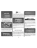
19. Drill 17/64” holes in the elevators for the
Joiner wire. Cut slots inboard of the holes to
allow the wire to be inset into the elevators, flush
with the LE. Sand the
Elevator LE
to a
“V”
shape to allow for Elevator travel — refer to the
plans for the correct angle.
❏
20. Test-fit the joiner wire into the Elevators.
Check to see that the Elevators align with each
other properly and that they fit the Stab without
binding. Make adjustments by
removing
the
Joiner Wire and then bending it, if required.
❏
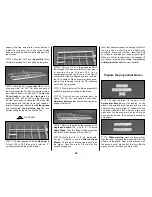
1. Cover the Fin/Rudder section of the plans
with waxed paper.
❏
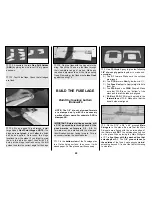
2. Punch out the die-cut 3/32” balsa ribs
V-1
through
V-6
. Be sure to preserve their jig tabs.
NOTE:
If you plan to install an operational
beacon light on top of the Fin drill a 3/16”
hole through the center (front to back, top
to bottom) of each rib. This hole will
provide a passage for the wiring.
❏
3. Cut a 15” length of the tapered 1/4” balsa
Stabilizer/Fin LE
stock to
match the plans
exactly
, as the length of the LE sets the angle of
the fin.
Notice that the Fin LE fits into a notch on
top of F-8.
❏
4. Punch out the die-cut 1/4” balsa
Fin TE
and lightly sand the edges to touch them up.
Sand (or cut) the tips to match the sweep angle
as shown on the plans.
❏
5. Sand an angle on the ends of each rib to
match the sweep angle of the LE and TE. Pin
ribs
V-1
and
V-6
to the building board over their
proper locations. Center the LE on the front of
the ribs and glue it in place. Center the Fin TE
on the aft edge of the ribs and glue it in place.
❏
6. Put ribs
V-2
through
V-5
into their places
and glue them to the LE and TE.
Remember, all
jig tabs should contact the work surface.
❏
7. Glue the die-cut 3/32” balsa
Fin Gusset
into the corner of V-6 and the Trailing Edge.
❏
8. Apply extra CA+ glue to any joints that do
not appear to be well glued.
❏
9. Blend the LE to match the ribs on the
upward facing (left) fin side. Sand the TE, if
necessary, to blend smoothly with the ribs.
❏
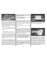
10. Make a skin for each side of the fin using
1/16” x 3” x 30” balsa sheet. Leave excess balsa
on one edge of the skin so it
overhangs past
V-1 about 5/8”
; this will allow fitting to the stab
later. With the structure flat on the table, glue on
the left (upward-facing) skin.
30"
3"
FIN SKIN
Build the fin
14
Summary of Contents for CESSNA 182 SKYLANE
Page 8: ...8 DIE CUT PATTERNS ...


