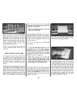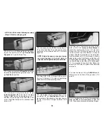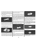
its correct length, then insert it from the servo
location through F-1 into the Connector on the
Nose Wheel Steering Arm. Clip the Metal Clevis
onto the servo horn. Align the servo horn and
Nose Wheel Steering Arm as shown on the
plans. Secure the Pushrod in the Quick
Connector with a 4-40 x 1/4” Socket Head
Cap Screw.
❏
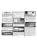
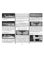
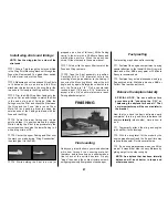
6. When the Nose Wheel Steering Arm is
adjusted, remove the Nose Gear Wire. File a flat
spot where the steering arm locking screw
contacts the wire so the steering arm can be
locked in position.
Depending on your choice of engine, 2-stroke or
4-stroke, you may have to be a little inventive for
throttle, tank and muffler hookup. The installation
of a 2-stroke .60 to .90 size engine is pretty
straightforward. Use the ser vo locations
provided on the Servo Tray, mount the tank
sideways as shown, and use a Top Flite In-Cowl
Muffler (TOPQ7916). Some 4-stroke engines
allow the throttle linkage to be rotated 180
degrees, thereby permitting the same servo
setup as a 2-stroke engine.
The O. S. .91
Surpass is one such engine.
This model flies very well on an O. S. .61 SF
2-stroke engine. As the .61SF also allows for the
most “sterile” setup with everything contained in
the cowl, we will detail its installation.
We have
also included instructions for those who prefer to
use one of the larger 4-stroke engines.
❏
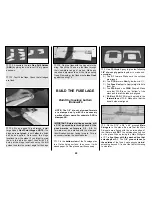
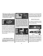
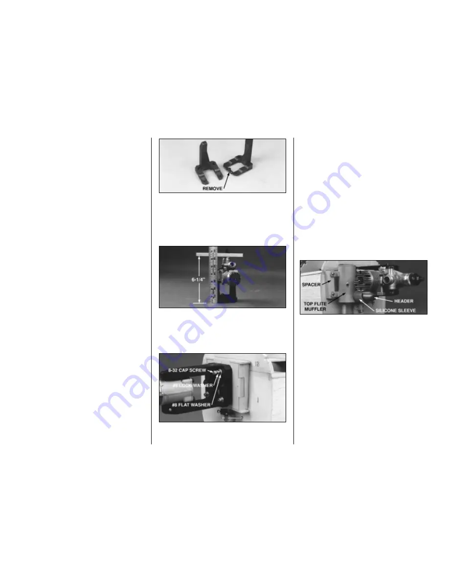
1. Remove the spacer bar from the back of
both Engine Mount halves and trim off any burrs.
Snap the Engine Mount halves together and
place the engine of your choice between the rails,
adjusting the width between the rails accordingly.
❏
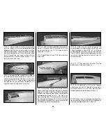
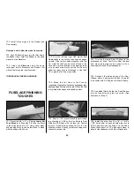
2. Position the engine so that the propeller
backplate is exactly 6-1/4” (159 mm) from the aft
edge of the Engine Mount. Mark, drill and tap
the engine mounting holes to accept the 8-32
socket head cap screws included with this kit.
❏
3. Install the Engine Mount on the Firewall as
shown with four 8-32 x 1-1/4” Socket Head Cap
Screws, #8 Flat Washers and #8 Lock Washers.
Use the index marks on the Firewall to center
the Engine Mount.
NOTE: We strongly recommend that ALL
engines be mounted horizontally to provide
enough cooling airflow over the cylinder
via the normal cowl air inlets.
❏
4. Bolt the engine to the mount.
If using the optional Top Flite In-Cowl Muffler
and Header, perform the following step:
❏
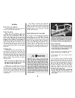
5. Bolt the Top Flite Header (not included) to
the engine. Use the Silicone Sleeve to attach the
Top Flite In-Cowl Muffler (not included) to the
Header. Make a spacer block for the muffler from
scrap.
NOTE:
Do
not
use balsa. Use epoxy to
glue the spacer block to F-1 in line with the
muffler mounting lugs. Shorten the muffler or
header connection tubes if required, so that the
muffler can be screwed to the spacer using the
supplied screws and silicone washers.
❏
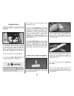
6. Drill a 3/16” hole through the Firewall in line
with the servo and throttle arm on the engine.
Keep the hole close to the level of the servo
tray
so that the pushrod will be able to pass
under the Fuel Tank.
Install engine and tank
36
Summary of Contents for CESSNA 182 SKYLANE
Page 8: ...8 DIE CUT PATTERNS ...

