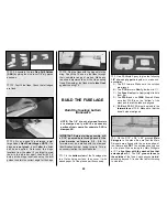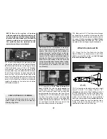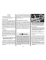
one end attached to a pin centered at the tail)
out to a wing tip. Put a piece of tape on the
string to mark the intersection of the string and
the wing tip. Swing the string over to the other
wing tip and check to see if the distances are the
same (see diagram). Adjust the position of the
trailing edge of the wing until the wing is
properly aligned.
NOTE: Make sure the wing is held securely
and cannot shift while you are drilling the
mounting holes.
❏
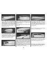
3.
Lightly
mark the center of the wing mount
holes on the Mounting Blocks, with a
1/4” drill
bit
inserted through the Bolt Plates in the wing.
Do
not
drill through the Mounting Blocks with
the 1/4" Bit.
❏
4.
Remove the wing
and drill the holes with a
#10
(or 13/64”) drill bit through the wing mount
blocks. Keep the drill as vertical as possible. Tap
the holes with a
1/4-20 tap
. Add a couple drops of
thin CA to the holes to harden the threads, then
re-tap the holes after the CA has fully cured.
❏
5. Bolt the wing in position with
1/4-20 x 2”
nylon
Wing Bolts
.
The nylon Wing Bolts may be
shortened to 1-1/2” if desired.
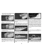
NOTE: Hinging is usually done after
covering and painting; however, because
the control linkages will be enclosed in the
fuse, you should temporarily install the
hinges WITHOUT using CA so that the
clevises can be adjusted. The hinge
locations are shown on the plans.
❏
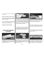
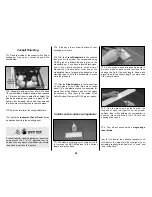
Cut 15 hinges (3/4” x 1”)
from the 2” x 9” CA hinge
strip. Trim the corners at a
45 degree angle to make
insertion easier.
❏
1. Use a
#11 blade
in a hobby knife to cut
matching hinge slots in the Stab and the
Elevators at the locations shown on the plans.
Test fit the Elevators to the Stabilizer with all
hinges
and
the wire joiner in place. Make sure
both Elevators are set at the same angle. Make
adjustments to the joiner wire and pushrod
length if necessary.
Do steps 2 and 3 AFTER the model has been
covered.
❏
2. Chamfer the ends of the joiner wire slightly
with a file. Roughen the “arms” with coarse
sandpaper. Clean the “arms” thoroughly with
rubbing alcohol. Work a generous amount of
30-Minute Epoxy into the wire joiner holes in
the elevators.
❏
3. Work the elevator hinges into the stab and,
as you do this, insert the wire joiner all the way
into the elevator holes. Wipe away any excess
epoxy. Glue the hinges in place using 4-6 drops
of
thin
CA on
both sides of each hinge.
❏
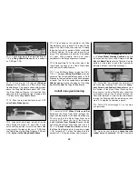
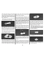
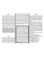
1. Hold the Rudder against the Fin. Mark the
location of the Torque Rod
tiller on the LE of the
Rudder. Drill a 1/8” hole into the Rudder LE that
is in line with the Torque Rod
tiller. A hand-
turned
Pin Vice is a good tool for this purpose.
❏
2. Cut a 1/8”-wide groove from the bottom of
the Rudder to the tiller hole. Ream out the
groove with a 1/8” drill bit or round file. Insert the
Torque Rod tiller into the hole, then seat the
Rudder against the Fin TE. Make whatever
adjustments are necessary to align the Rudder
in the neutral position. Double check that the
servo is centered.
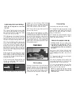
Hinge the rudder and ailerons
Hinge the elevator
1"
1"
3/4"
HINGE THE CONTROL
SURFACES
42
Summary of Contents for CESSNA 182 SKYLANE
Page 8: ...8 DIE CUT PATTERNS ...

