❏
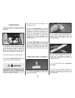
3. We installed a pushrod tube (not included
in the kit) along the bottom inside surface of the
fuse, to serve as a conduit for the antenna. The
antenna was then inserted and pushed to the aft
end of the fuse.
❏
4. The Receiver and Battery may be “wedged”
in place under the servo tray with additional
layers of foam rubber.
❏
5. Make sure the control surfaces move in the
proper direction as illustrated in the following
sketches:
❏
6. Adjust your pushrod hookups as necessary
to provide the control surface movements shown.
NOTE: The surface throws and balance for
this aircraft have been extensively tested. We
are confident that they represent the settings
at which the Cessna 182 flies best. Please set
up your aircraft to the specifications listed
above. If, after a few flights, you would like to
adjust the throws to suit your tastes, that is
fine. The Cessna 182 has large elevators and
does not require much throw. Too much
throw can force the plane into a stall, so
remember... “More is not better.”
NOTE: This section is VERY important and
must NOT be omitted! A model that is not
properly balanced will be unstable and
possibly unflyable.
❏
1. Accurately mark the balance point on the
bottom of the wing on both sides of the fuselage.
The balance point is shown on the plan (
CG
),
and is located
4” (102 mm) back from the
leading edge at the wing root
as shown in the
sketch and on the plans. This is the balance point
at which your model should be balanced for your
first flights. Later, you may wish to experiment by
shifting the balance up to
3/8” forward or 1/4”
back
to change the flying characteristics. Moving
the balance
forward
may improve the
smoothness and tracking, but it may also require
more speed for takeoff and make it more difficult
CG
4"
Balance your model
CONTROL SURFACE THROWS
:
We recommend the following control surface
throws:
NOTE:
Throws are measured at the
widest
part
of the elevators, rudder, and ailerons.
NOTE: If your radio does not have “dual
rates”, then set up the control surfaces
to move at the high rate throws.
ELEVATOR:
(High Rate)
1-1/16” up
1-1/16” down
(Low Rate)
3/4” up
3/4” down
RUDDER:
(High Rate)
1” right
1” left
(Low Rate)
5/8” right
5/8” left
AILERONS:
(High Rate)
5/8” up
5/8” down
(Low Rate)
1/2” up
1/2” down
FLAPS:
(Takeoff)
1” down
(Landing)
2” down
TRIM MIXING:
If your transmitter is
programmable for Flap to Elevator mixing we
determined during our flight tests that attitude
control was smoother with 3/16” of
down
Elevator trim at half Flaps and 3/8” of down
elevator trim at full Flaps.
4-CHANNEL
TRANSMITTER
4-CHANNEL
TRANSMITTER
4-CHANNEL
TRANSMITTER
4-CHANNEL RADIO SETUP
(STANDARD MODE 2)
TRANSMITTER
4-CHANNEL
ELEVATOR MOVES UP
RIGHT AILERON MOVES UP
LEFT AILERON MOVES DOWN
RUDDER MOVES RIGHT
CARBURETOR WIDE OPEN
52
Summary of Contents for CESSNA 182 SKYLANE
Page 8: ...8 DIE CUT PATTERNS ...


