10
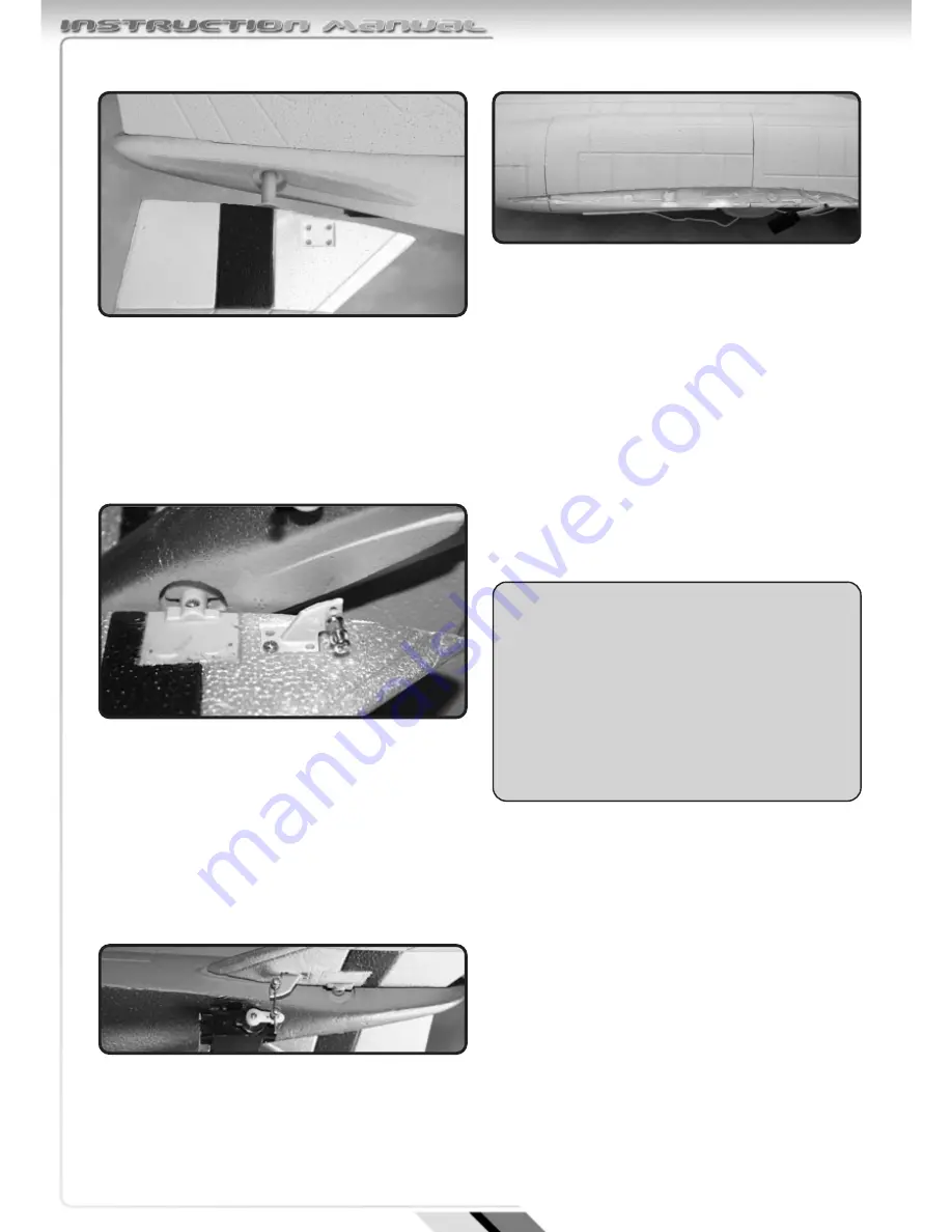
Test fit the two horizontal stabiliser panels.
The joiners pass through a tube at the rear of the
fuselage.
The panels should be angled downwards. (anhedral)
Fit the two fixing screws to lock the joiner in place.
Locate the elevator pushrod, control horn, fixings
and backplate.
position the control horn on the moulded recess on
the elevator in line with the servo arm and fix in
place with screws and backplate.
Insert the pushrod through the clamp connectors in
the servo arm and control horn.
Align elevators with mould line in fuselage and
gently tighten connectors until the controls are
checked.
Remove excess length of pushrod with wire
cutters.
Test fit the two wing panels on to the fuselage
Apply adhesive to the contact faces on the wing and
fuselage and press firmly together use pins or tape
to hold in place.
Wipe off any excess adhesive and allow to dry.
Repeat procedure for the other wing panel.
SECTION 5: FINAL SET UP
Ensure that transmitter is switched on with throttle
down and all trims central.
Open the hinged battery bay door by turning the
catches.
Insert into the battery and ensure that battery and
ESC leads project out of the aperture.
Connect the battery and ESC leads together
Red-red and Black-Black and close the battery
cover using the catches to lock it in place.
Uncoil the receiver aerial and fully extend to hang
off the rear of the aircraft.
WARNING
With the battery connected and the model
switched on the motor is live. The Electronic
speed controller (ESC) will go through its start
up procedure and will emit a series of beeps
while it configures throttle positions. The
motor could start unexpectedly and we
recommend that the model is restrained during
handling.
Summary of Contents for F-4E Phantom
Page 1: ......


