11
£
2
LANDING GEAR ASSEMBLY
Mains
The main gear struts are formed from 1/8” music wire, you will need to solder a #8 washer to the gear
leg to act as a stop on the inboard side of the wheel. On the outboard side a 1/8” wheel collar is used to
retain the wheel. If you are not familiar with silver soldering, see the Shop Tips section on my web site
www.topnotchkits.com.
£
1 Solder a #8 washer to each gear leg as shown in the photo below.
Refer to the stack order of the gear strut cover
on the plans sheet. Lay the parts out as shown
on the right to assemble a left and a right strut
cover. Glue LGD to LGB.
£
3 Glue the LGD and LGB assembly to LGA.
£
4 Use the formed wire landing gear as a spacer
and then glue LGC to LGA leaving a slot for
the gear strut.
£
5
Sand a 45° bevel on LGA at the wide end (top)
to allow clearance for the fuselage. Sand only
down to the ply core (LGD).
£
6 Install the landing gear and retain it with two 1/16” ply landing gear straps and four #2 x 1/4” S.M.
screws. Temporarily install a hinge into the strut cover assembles and test fit them onto the gear. Mark
the location of the outer most center hinge hole on the fuselage, drill a 1/16” hole for a #2 x 1/4” S.M.
retainer screw and install.
£
7 Install the 1/16” ply gear retainer clip in the hole provid-
ed at the bottom of the strut. The strut cover installation is
now complete. Do not install permanently until after cover-
ing. Use a small dab of Epoxy in the hinge slot to retain the
hinge. Be sure to add about 3° of toe in to the gear leg before
final assembly.
The strut cover parts are laid out to assure a left and right assembly. Note that the
parts on the right, LGD and LGB have been assembled and a hinge (painted black
for clarity) has been laid in position in the hinge slot in LGD. The hinge will be
permanently installed after assembly.
The installed strut cover is hinged to the fuselage at the top to allow it to flex with
the gear leg. A #2 x1/4” S.M. Screw and ply retainer tab is used to secure it at the
bottom. A #8 washer has been soldered to the inboard side of the gear to retain the
wheel, a 1/8” wheel collar is used on the out board side.
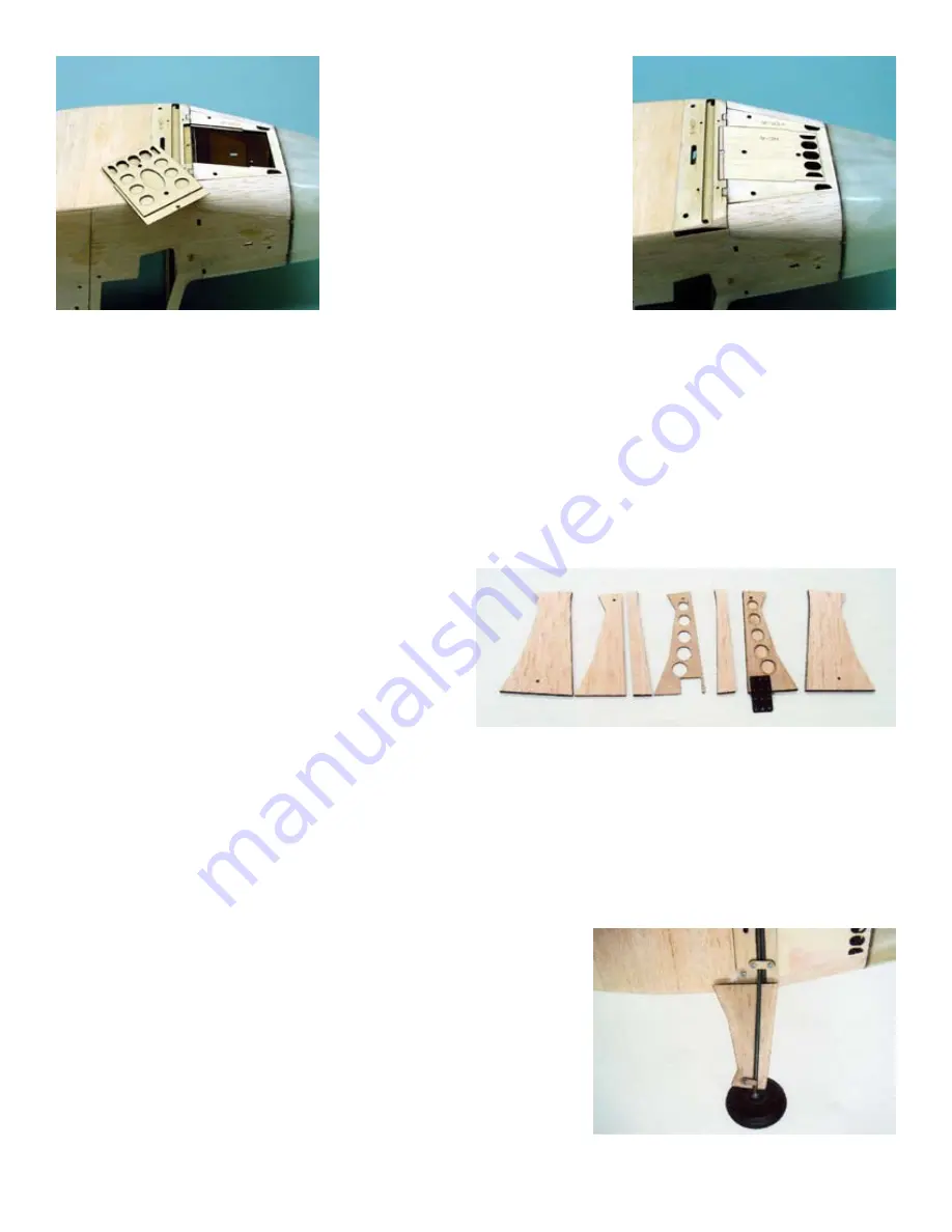
The photo on the left shows the assembled battery
hatch cover ready to be installed. The shape of these
parts will enable the cover to key into position in the
hatch cover opening and provide a secure opening for
accessing the flight pack.
In the photo on the right, the battery hatch cover has
been installed. The flange on the front of the hatch
cover will retain the front of the cover while a #2 X
3/8” sheet metal screw retains the cover. Note that the
aft edge of the cover has been sanded to contour with
the bottom of the fuselage.


