background image

Page 8

£

19

£

18

£

17

£

16

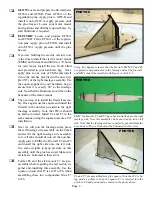
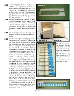
Sand the leading edge of the wing panel flat. 

Apply  aliphatic  resin  glue  and  install  the 

leading edge. Use pins and tape to secure it 

until cured.

Sand the wing tip flat and then install W12. 

Secure it with pins and tape until cured.

Sand the root section flat.

PHOTO U

Use a razor plane and sanding block to round 

off  the  leading  edge  to  the  desired  airfoil 

shape. First plain or sand the leading edge to 

contour with the ribs and then rounding off 

the  remaining  material  easily  accomplishes 

this.

This completes the assembly of one-wing panel repeat steps 1 through 19 for the second panel. Note that 

you will not need to install wing joiners in the second panel.

£

20

Test fit the two wing panels together. They should fit snugly with very little gap at the center. Sand as 

required to get a good fit. Apply Epoxy or aliphatic resin glue to all mating parts and then slide the wing 

halves together. When cured, apply the 1” fiberglass tape with thin CA.

£

21

Place the finished wing on the bench. Generally one panel will be slightly heavier then the other. Add 

weight to the lighter panel until the wing balances.

This completes the wing assembly.

Covering your Li’l Pup.

If you going to fly the Li’l Pup with glow power you will need to cover the entire model to fuel proof it. However 

if you are going to fly your Li’l Pup with electric power the only part that must be covered is the wing. The fuse

-

lage and empennage can be covered, painted or just left as raw wood if desired.

Follow the instructions supplied with the covering material that you select. It is much easier to cover all the indi-

vidual parts before the final assembly. 

After covering you can install and glue the empennage and the 3/16” dowels permanently. 

Balancing the Li’l Pup.

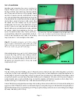
To balance the Li’l Pup for first flights, install the Balance Points into the slots provided in the bottom of the wing 

just ahead of the spar at W3. Temporarily slide one balance point into each these slots, the model should balance 

level when supported on your fingers at these points. Place the wing onto the model and secure it with rubber 

bands. If the model does not balance, move the battery pack and controller to achieve balance. In some cases you 

may have to ad weight to achieve the correct balance. Make sure that your battery pack and all radio components 

are securely fastened before flying your Li’l Pup. Once balance has been achieved you can remove the balance 

points.

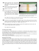
A strip of fiberglass cloth  over the center joint will add consid

-

erable strength to the wing. This one was brushed with thinned 

Epoxy resin but you can also use thin CA to attach it.

Summary of Contents for Li'l Pup

Page 1: ...Top Notch Products Li l Pup Assembly Manual Top Notch Products Company P O Box 1051 Goodlettsville TN 37072 Phone 615 866 4327 www TopNotchKits com ...

Page 2: ... glue Two common brands are Elmer s and Titebond However to really speed things up you may want to also get some Cyanoacrylate also known as CA type adhesives in thick and thin viscosities During the assembly sequences you will be directed to locate and prepare parts If you look in the back of this manual you will see several pages called Parts Locator Just locate the part in the alphabetical list...

Page 3: ...nd D Locate F9 and test fit it onto the pins Remove F9 and apply glue to the side that will face FSD L then return it to the pins and hold it firmly into contact with FSD L until the glue has cured c Move the pins to holes A and E on the fuselage side FS L Test fit the FSD L as sembly to FS L and then remove it from the pins apply glue and reinstall it onto the pins Hold it firmly into contact wit...

Page 4: ...hould be facing forward Install F2 and F3 in the same manner using the square to assure a 90 installation 5 Next we will join the fuselage sides place the left fuselage side assembly on the bench and test fit the right fuselage side assembly to it All tabs should fit into all the notches Apply glue to EMM the Firewall F2 and F3 and install the right side onto the left side Use some weights to keep...

Page 5: ...stra tion pins and then glue and install HA B Note and observe the correct direction of HA B labeled on the part The fuselage bottom sheeting is composed of seven sections that must be assembled before installing They are BS 1 through BS 7 Note that BS2 and BS7 are 1 16 ply and all remaining sections are 1 16 balsa Locate and prepare BS1 BS2 BS3 BS4 BS5 BS6 and BS7 Test fit these sections together...

Page 6: ...u can install the 3 16 dowels and the skids now 14 Locate the stabilizer ST and the vertical fin FN and prepare them Use the square and glue the vertical fin to the stabilizer Sand the leading edges to a slight radius This assem bly can be installed now or after covering if desired 15 Locate the rudder RU and one of the con trol horns CH The control horn must be installed on the right side of the ...

Page 7: ...hod to install the tip sheet ing TS 3 Locate and prepare seven bottom cap strips Bottom Caps Glue one into each location between LES B and TES B Note that they will fit into the notches provided 4 Locate and prepare the false leading edge FLE Test fit this into the notches in the leading edge sheeting When satisfied with the fit Glue to LES B Make sure FLE is bot tomed in the slots and held firmly...

Page 8: ...in W1 for them Cut and remove the material indicated just behind FLE both sides of the spar and just ahead of the trail ing edge spar See the photo N for the correct locations 11 Locate and prepare WJ1 two WJ 2 s and one WJ 3 Test fit these parts and when satisfied with the fit apply glue and install Use some cloths pins or other clamps to assure good contact with the mating surfaces PHOTO M When ...

Page 9: ...eting Apply aliphatic resin glue to ribs W1 W2 W3 and W11 in their entirety Apply glue to all remaining ribs from the spar to the false leading edge and from the trailing edge to the trailing edge spar Along the entire false leading edge and along the entire trailing edge spar At this point everything under the top sheeting except the trailing edge and the top spar will have glue applied Apply a b...

Page 10: ... Pup with glow power you will need to cover the entire model to fuel proof it However if you are going to fly your Li l Pup with electric power the only part that must be covered is the wing The fuse lage and empennage can be covered painted or just left as raw wood if desired Follow the instructions supplied with the covering material that you select It is much easier to cover all the indi vidual...

Page 11: ...y club and they will arrange to help you get up to speed so you can enjoy the greatest hobby sport on the planet To locate a club in your area and get a contact number ask at your local hobby shop or check the Academy of Model Aeronautics web site http www modelaircraft org For information on a club and sanctioned flying site near you Photo W To simplify working on your Li l Pup a handy plywood st...

Page 12: ...X 4 X 7 AC Ply Fuselage Former F6 1 1 1 16 X 4 X 7 AC Ply Fuselage Former F7 14 1 3 32 X 4 x 36 Balsa Fuselage Former F8 14 1 3 32 X 4 x 36 Balsa Fuselage Former F9 16 2 1 64 X 2 X 8 Ply Fuselage Wing Saddle FLE 11 2 1 8 X 4 X 36 Balsa False Leading Edge FN 11 1 1 8 X 4 X 36 Balsa Vertical Fin FSD L 5 1 1 16 x 4 x 36 Balsa Left Fuselage Side Doubler FSD R 5 1 1 16 x 4 x 36 Balsa Right Fuselage Sid...

Page 13: ... W1 2 1 1 16 x 4 x 36 Balsa Wing Rib 1 W1 6 1 1 16 X 3 X 36 Balsa Wing Rib 1 W10 4 1 1 16 X 3 X 36 Balsa Wing Rib 10 W10 9 1 1 16 X 3 X 36 Balsa Wing Rib 10 W11 4 1 1 16 X 3 X 36 Balsa Wing Rib 11 W11 9 1 1 16 X 3 X 36 Balsa Wing Rib 11 W12 14 2 3 32 X 4 x 36 Balsa Wing Rib 12 W2 2 1 1 16 x 4 x 36 Balsa Wing Rib 2 W2 6 1 1 16 X 3 X 36 Balsa Wing Rib 2 W3 2 1 1 16 x 4 x 36 Balsa Wing Rib 3 W3 6 1 1...

Reviews: