Page 6
£
8
Locate and prepare the top spar section (SP-
T). Test fit this to the bottom spar section and
when satisfied with then fit, glue it to the bot
-
tom spar section. Secure it with straight pins
until the glue has cured.
£
7
Locate and prepare the wing ribs W1 through
W11. Put W1 aside for now, it will be in-
stalled after the top spar section has been
installed. Place each rib into its respective
location. Make sure each tab is bottomed in
the appropriate notches before applying and
glue.
£
6
Locate and prepare the trailing edge spar
(TES). When satisfied with the fit, glue LES
to TES-B.
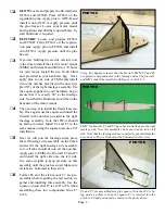
The wing bottom sheeting assembly with FLE (right), SP-B
(Center) and TES (left) installed.
PHOTO L
£
10
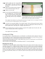
On the first wing panel we will also install
the wing joiners. To do this we must first cut
the openings in W1 for them Cut and remove
the material indicated just behind FLE, both
sides of the spar and just ahead of the trail-
ing edge spar. See the photo N for the correct
locations.
£
11
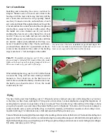
Locate and prepare WJ1, two WJ-2’s and one
WJ-3. Test fit these parts and when satisfied
with the fit, apply glue and install. Use some
cloths pins or other clamps to assure good
contact with the mating surfaces.
PHOTO M
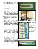
When installing ribs, make sure they are bottomed in there slots
and in good contact with the bottom sheeting before applying
glue.
£
9
Install W1 at this time. Note that the spar,
FLE and TES all have the dihedral angle cut
into them. Make sure W1 is seated into these
components for the correct dihedral angle
Remove material in these areas.
Photo N: In preparation for installing the wing joiners on this
wing section, the material indicated must be removed.
Poto O: The ply wing joiners have been attached and are
clamped in place with cloths pins until the adheasive has set.
PHOTO N
PHOTO O

