background image

72

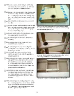
Locate and assemble the rudder, use the 

registration pins to laminate the three sections 

together. NOTE: The water rudder is the clear 

plastic part located in the parts bag. This water 

rudder should be attached to the rudder with a 

#2-56 bolt and Ny-Lock nut. It should be left 

loose enough to kick up in the event of contact 

with weeds or other objects. Also the rudder 

should be water proofed with a coat of thinned 

Epoxy resin before final assembly.

1

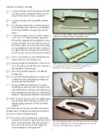
The rudder is laminated from three sections, the ply center 

section has cutouts for the hinges and the kick-up water 

rudder is mounted to the  bottom. 

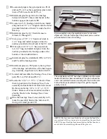
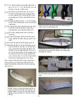
Now is a good time to assemble the Hinge Slotting jig. Use it to 

cut the slots for the CA hinges in the trailing edge of the stabilizer 

and the slots for the pinned hinges in the vertical fin. Place the 

jig against the edge to be slotted, keep the knife parallel to the 

part and make several shallow passes until the desired depth is 

reached. The hinge locations are marked on the elevator, transfer 

these markings to the stabilizer and cut the slots. Place the pinned 

hinges into the rudder and then use this to locate the slot locations 

on the vertical fin.

Wing Assembly

The wing plans may be used in one piece or 

cut in half if desired. Place them on the work

­

bench and cover them with waxed paper.

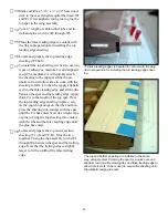
Locate and prepare the false leading edge 

(FLE). Use a straight edge to align it with the 

plans. Note that the alignment line at the root 

end of the plans should align with the align­

ment line on the first standoff. Tack glue a 

pinning to every other stand off and secure to 

the bench with pins.

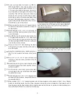
The wing leading edge is secured to the bench by tack gluing 

pinning tabs to every other standoff and securing with pins. 

A straight edge is used to insure it is straight and it is aligned 

with alignment lines on the plan and the first standoff.

11

Summary of Contents for Seamaster II

Page 1: ...TOP NOTCH PRODUCTS Seamaster II Top Notch Products Company PO Box 1051 Goodlettsville TN 37070 www topnotchkits com...

Page 2: ......

Page 3: ...n CA I recommend the Dave Brown pipet s available at your hobby shop Be sure to stretch the end pull it with a pair of pliers to a thin applicator tip as they are not supplied in this configuration an...

Page 4: ...ue the F5 and F6 assembly to the RIGHT fuselage side c 8 Locate the Wing Mounting Plate and two 10 32 blind nuts Press the blind nuts firmly into the holes provided in WMP Because WMP and F8 interlock...

Page 5: ...amounts of FB extending on each side Installing the fuselage bottom a piece of scrap balsa is bev eled as required to provide the clamps a flat surface to grip c 19Glue the fuselage sides to FB c 20...

Page 6: ...p of the aft fuselage and formers F8 F9 and F10 Taper as required at the tail section HINT Cut both pieces of triangle stock from the same stick this will improve the odds that both sticks will be abo...

Page 7: ...o F3 F4 and F5 and the fuselage sides The windshield and FST have been installed and the water resistant hatch has been assembled This photo shows the nose cone installed however we will get to that a...

Page 8: ...izer Cut two pieces of triangle stock and glue them at the interface of the vertical fin and the stabilizer Place the fuselage assembly on the building bench and weight it down to insure that it is se...

Page 9: ...s side will be the front of the firewall facing for ward Install triangle stock at the base of the vertical fin and fair it in the front to match the contour of the Ny Rod FRONT BACK Here the electric...

Page 10: ...glow version do not remove the circular openings in PHB These are cooling air exits for the electric version There are four 1 16 tabs attaching the hatch to the power pod sides trim these tabs and re...

Page 11: ...leading edge and glue them to the bottom of the forward fuselage bottom using the alignment lines provided starting at the step Optional Landing Gear Assembly Locate MPG A and two MGP B parts Use the...

Page 12: ...ertion into the axle holes This fit must remain snug Plastic tail gear mount halves will replace the water rudder for land op eration Cut a piece of the 1 16 wire to the same width as the gear mount a...

Page 13: ...he edge to be slotted keep the knife parallel to the part and make several shallow passes until the desired depth is reached The hinge locations are marked on the elevator transfer these markings to t...

Page 14: ...aptive in the sheer web c 6 Place a 3 16 x x 24 basswood spar n position over the plans c 7 Place the leading edge tab of each rib into the appropriate slot in the false leading edge and down over the...

Page 15: ...ly thick CA to the length of the top spar Place the top leading edge sheeting in place cen ter the cap rib openings on the ribs and then press the sheeting into contact with the spar until the CA has...

Page 16: ...ply reinforcing ring around the servo lead hole c 26 Install and glue the servo mounting rails SMR The side with the screw holes should be facing each other c 27 Assemble the bottom wing tip sheeting...

Page 17: ...and C c 37 Install and glue the aft sheeting section D c 38 Install and glue the forward sheeting assem bly note that you may have to wet the sheet ing to make the bend without breaking Use Windex or...

Page 18: ...e fuselage and cen ter it Glue the TEX assembly to the trailing edge taking care to keep it centered Use a mixture of Z Poxy thinned with dena tured alcohol to apply the 3 wide fiberglass cloth Lay th...

Page 19: ...ld line up with the slot on AB c 5 Taper the leading edge and the aileron horn block to contour with the ribs do not taper the tabs yet c 6 Install and glue the top sheeting AT The aileron horn should...

Page 20: ...LPLY 1 8 X 4 X 36 BWT A 2 21 BALSA 3 16 X 4 X 36 BWT B 2 21 BALSA 3 16 X 4 X 36 C 2 22 BALSA 3 32 X 4 X 36 CR 1 6 LPLY 1 4 X 4 X 18 D 2 22 BALSA 3 32 X 4 X 36 EV 1 21 BALSA 3 16 X 4 X 36 F1 1 6 LPLY...

Page 21: ...A 1 16 X 4 X 36 FT 4 1 16 BALSA 1 16 X 4 X 36 FT 5 1 16 BALSA 1 16 X 4 X 36 FTE 2 4 BALSA 1 8 X 4 X 36 FW E 2 7 ACPLY 1 8 X 6 X 28 FW G 2 7 ACPLY 1 8 X 6 X 28 HA 1 8 ACPLY 1 16 X 5 X 30 HAC 2 3 LPLY 1...

Page 22: ...3 X 36 SW T 2 23 BALSA 3 32 X 3 X 36 T 12 14 BALSA 1 16 X 4 X 36 TC A 1 18 BALSA 1 16 X 4 X 36 TC A 1 15 BALSA 1 16 X 4 X 36 TC B 1 17 BALSA 1 16 X 4 X 36 TC B 1 16 BALSA 1 16 X 4 X 36 TE 2 2 BALSA 1...

Page 23: ...7 1 10 BALSA 1 16 X 3 X 36 W7 1 11 BALSA 1 16 X 3 X 36 W8 1 10 BALSA 1 16 X 3 X 36 W8 1 11 BALSA 1 16 X 3 X 36 W9 1 10 BALSA 1 16 X 3 X 36 W9 1 11 BALSA 1 16 X 3 X 36 WBLES 1 18 BALSA 1 16 X 4 X 36 WB...

Page 24: ...Top Notch Products Company PO Box 1051 Goodlettsville TN 37070 www topnotchkits com...

Reviews: