background image

p

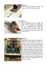
Step 41

Du-Bro  steel  landing  gear  straps  are 

used to retain the landing gear leg.

p

Step 42

When  opening  up  the  cowl,  give  the 

motor  plenty  of  space  for  cooling  air. 

This  is  a  fi berglass  cowl  fabricated 

for  the  prototype  model.  Install  the 

mounting  screws  so  they  screw  into 

the 1/4” ply fi rewall and then harden the 

holes with CA.

p

Step 43

Installation of the servo’s. Note that the 

center  push  rods  utilize  a  Z-bend  to 

maintain a low profi le to allow space for 

the aileron servo. Make sure all linkages 

are snug with no play. Note that a small 

amount  of  material  was  removed  from 

the fuselage doubler to allow clearance 

for the throttle linkage connector block. 

Temporarily install all linkages, the motor 

and the fuel system before covering. You 

may have to remove a small amount of 

material at the corner of the fi rewall for 

muffl er  clearance  depending  on  your 

choice of motor. 

12

Summary of Contents for SPUNKY

Page 1: ...SPUNKY ASSEMBLY MANUAL...

Page 2: ...gluing these parts at the laser cut edge it is important to use the correct adhesive It is recommended that you use only medium or thick Cyanoacrylate CA Aliphatic resin or Epoxy on these joints Use o...

Page 3: ...the notches in the front edge of the fuselage see the photo in step 3 pStep 3 The fuselage sides should look like this The triangle stock at the front of the fuselage will support the motor mount when...

Page 4: ...ssembly over and glue all three parts to the other side Run a bead of medium CA along all joints for added strength pStep 7 Measure 2 1 2 from the fuselage end and mark the inside of the triangle stoc...

Page 5: ...asking tape until cured such as aliphatic resin Now glue F 4 permanently into position pStep 11 Glue on the 1 8 Balsa wing saddle doublers and then snap the wing mount plates temporarily into position...

Page 6: ...time to sand all sides of the basic fuselage smooth Sand all corner radius s at this time as well pStep 15 Assemble the top deck plate and formers D 1 through D 4 and the top deck keel in place in th...

Page 7: ...se components out When assembling the fin and stabilizer components use the marks on the parts sand all these components out When assembling the fin and stabilizer components use the marks on the part...

Page 8: ...sets That way you can not go wrong Also take care to align the parts with each other pStep 23 Glue the leading edge in place at W 1 and W 5 Then adjust each rib to seat in the slots in the leading edg...

Page 9: ...all wing joints at this time pStep 26 Add the 3 32 sheer webbing the full length of the wing at the front of the spar Add 3 32 sheer webbing between W 1 W 2 and between W 2 W 3 to the back of the spa...

Page 10: ...from the building board and snap off the pinning tabs and breakaway feet on the false trailing edge Starting at the center of the wing lay the leading edge sheeting against the ribs and glue it Lay th...

Page 11: ...ing joiner is assembled from six parts they are the 1 4 core two 1 16 balsa sides two 1 16 ply sides and a 2 1 2 x 1 4 dowel This assembly performs several functions in addition to aligning the wing i...

Page 12: ...rward center section sheeting and it need only be placed in position and glued pStep 35 The top and bottom center section sheeting has been cut slightly oversized to accommodate variations in position...

Page 13: ...the servo cable exit You will need to enlarge the servo hole to accommodate your servo pStep 39 Assemble the ailerons and aileron leading edges sand to shape and then test install the hinges and the a...

Page 14: ...nstallation of the servo s Note that the center push rods utilize a Z bend to maintain a low profile to allow space for the aileron servo Make sure all linkages are snug with no play Note that a small...

Reviews: