10
PLASTIC WELDING STATION
EN
Translation of the original instructions
APPLICATION
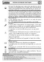
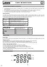
This tool allows the heating of plastics via a hot air flow.
POWER SUPPLY
1.
Connection
Connect the power cord to the station and plug the other end into an electrical outlet.
Once the connection is established, the device can be switched on.
2. Power supply switch
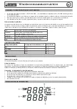
The power switch is used to switch the plastic welding station on and off. The air control switch turns the LCD screen and the air
flow rate on and off (there is a one-minute delay before it stops).
• Turn the air control switch to ON before use. Turn on the unit by pressing ON (POWER switch).
•
The user can adjust the air flow and temperature.
3. Air flow and temperature adjustment
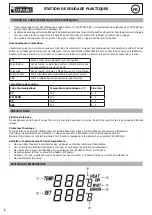
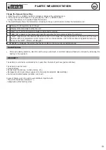
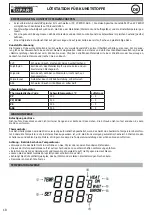
After adjusting the air flow and temperature control knob, wait for the temperature to stabilise for a short period of time. To adjust
the temperature, refer to the table «Welding temperature».
4. Air flow
Set the knob according to the surface to be heated. When the working temperature is above 450°C, the air flow control knob must
be set on a higher setting than 4 or the machine might be damaged.
5. Système de refroidissement automatique
•
When the work is finished, the user can do the following operations :
- Set the temperature to 160°C, then set the air control switch to OFF; the display turns off. The delayed cooling function
of the air pump continues to provide cooling for 1 minute. Set the knob to the OFF position.
- Set the temperature to 160°C. Allow the air pump to run for 1 minute. Set the button to OFF.
6. Turn off the power switch
If the unit is not used for a long period of time, unplug the unit.
TECHNICAL FEATURES
Electrical
power (W)
Power supply
voltage (V)
Frequency
(Hz)
Air pump
Capacity
(L/min)
Hot air
temperature
320 W
220 – 240 VAC
50
Diaphragm pump
24 L/min
160 – 480°C
Accessories : 1 heating nozzle for the hot air gun and 1 power cable.
REPAIR
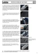
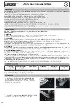
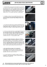
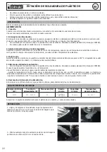
1. Clean and degrease the damaged area, then lightly sand the
plastic on a 15 to 20 mm strip on either side of the tear to remove
paint and other impurities.
2 - Remove any risk of subsequent extension of the tears by drilling
a Ø 3 mm hole at each end.


