th
6
6
6
Chapter 3
Interface
3. Input/output interface type
3. .1 Digital input interface
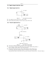
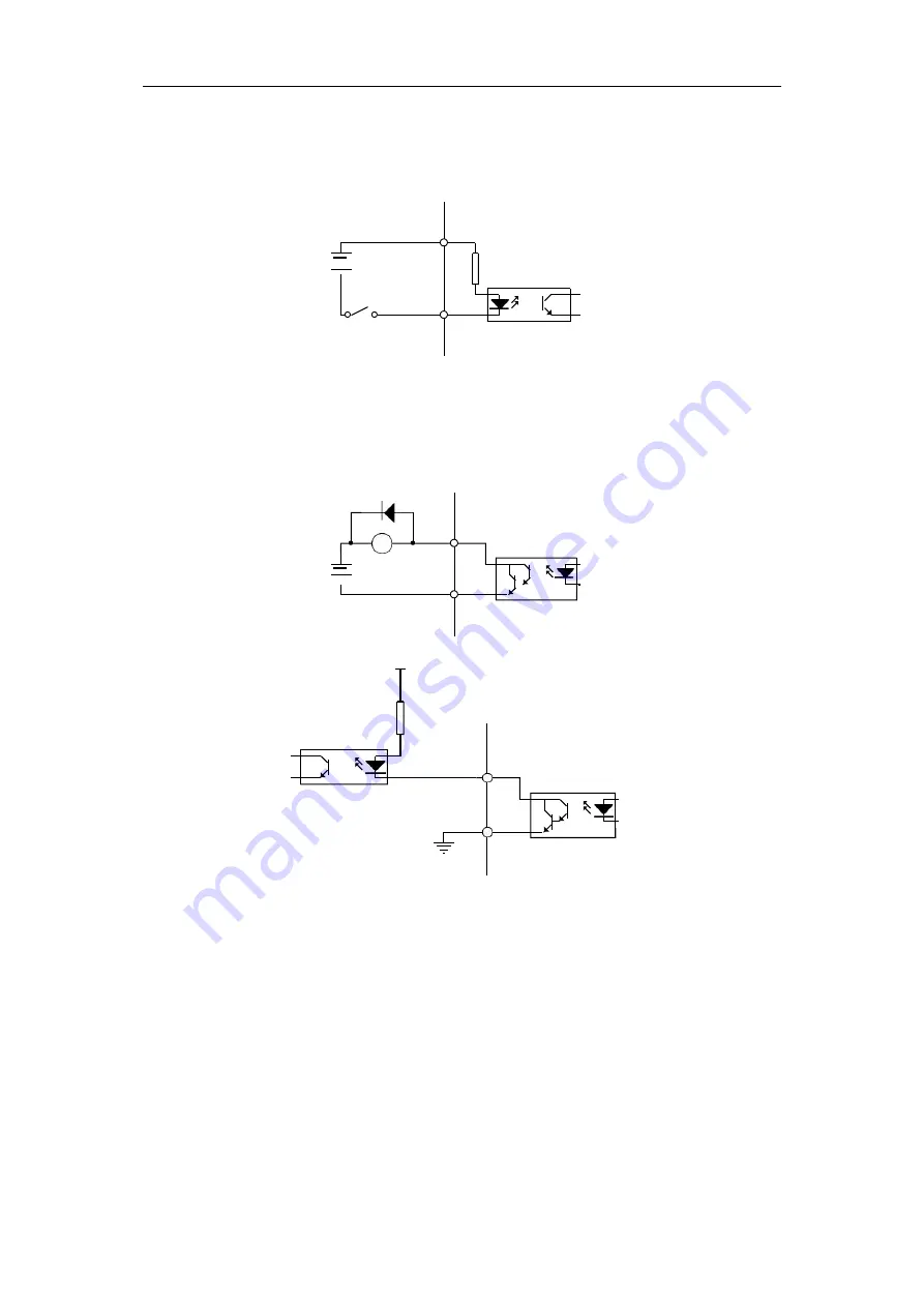
Figure 3.3
Type1 digital input interface
Power supply by the user, DC12~24V, current ≥100mA;
Note that if the current polarity is reversed, the servo drive will not work.
3. .2 Switch output interface
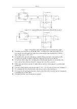
a. Relay connection
VCC
max 25V
max 50mA
servo amplifier
b. Optocoupler connection
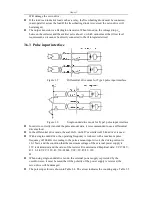
Figure 3.4
Type2 digital output interface
The output is a Darlington transistor connected to a relay or optocoupler;
The external power supply is provided by the user, but it must be noted that if the polarity of
the power supply is reversed, the servo drive will be damaged;
The output is in the form of an open collector with a maximum current of 50mA and an
external power supply with a maximum voltage of 25V.Therefore, the load of the digital
output signal must meet this limit.If the limit is exceeded or the output is directly
servo amplifier
COM+
12~24V
4.7K
SW
servo amplifier
max50mA
max25V
connecte to e power supp y,
Summary of Contents for SD300
Page 87: ......
Page 89: ...Chapter 7 Running 7 9 2 Operation l Set the parameter values ...

