6
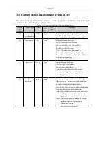
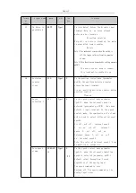
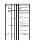
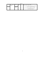
Chapter 3
Interface
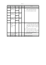
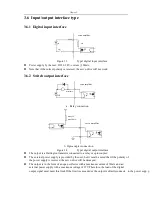
Will damage the servo drive;
If the load is an inductive load such as a relay, the freewheeling diode must be connected
in anti-parallel across the load.If the freewheeling diode is reversed, the servo drive will
be damaged;
The output transistor is a Darlington transistor. When turned on, the voltage drop v
ce
between the collector and the emitter set is about 1v, which cannot meet the ttl low level
requirement, so it cannot be directly connected to the ttl integrated circuit.
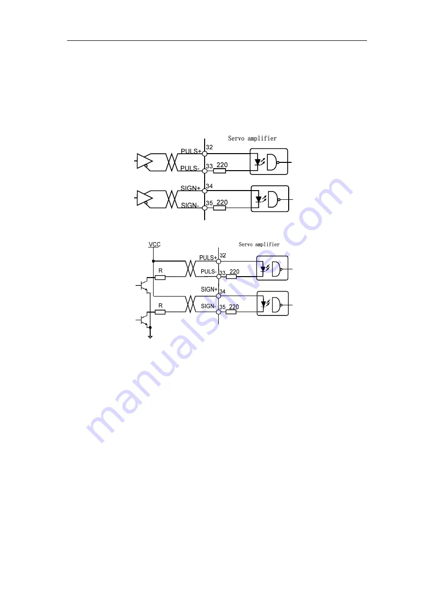
3. .3 Pulse input interface
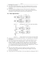
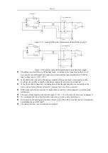
Figure 3.5
Differential drive mode for Type3 pulse input interface
Figure 3.6
Single-ended drive mode for Type3 pulse input interface
In order to correctly transmit the pulse amount data, it is recommended to use a differential
drive method.
In the differential drive mode, the am26ls31, mc3487 or similar rs422 line driver is used.
With a single-ended drive, the operating frequency is reduced, with a maximum pulse
frequency of 200 kHz.According to the pulse amount input circuit, the driving current is
10~15mA, and the condition that the maximum voltage of the external power supply is
25V is determined, and the value of the resistor R is determined.Empirical data: VCC=24V,
R=1.3~2k; VCC=12V, R=510~820Ω; VCC=5V, R=82~120
Ω
。
When using single-ended drive mode, the external power supply is provided by the
user.However, it must be noted that if the polarity of the power supply is reversed, the
servo drive will be damaged.
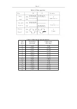
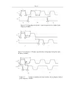
The pulse input form is shown in Table 3.4. The arrow indicates the counting edge. Table 3.5
Summary of Contents for SD300
Page 87: ......
Page 89: ...Chapter 7 Running 7 9 2 Operation l Set the parameter values ...

