Chapter 3
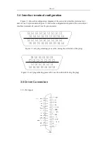
Interface
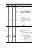
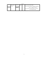
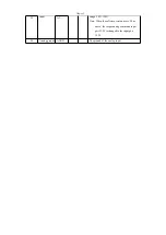
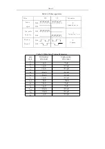
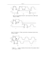
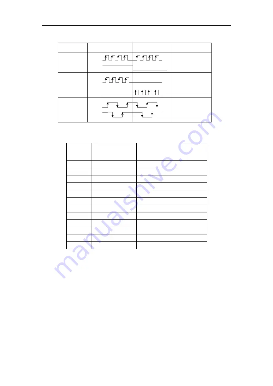
Table 3.4 Pulse input form
Table 3.5 Pulse Input Timing Parameters
para
mete
r
Differential
drive input
Single-ended
drive input
t
ck
>2μS
>5μS
t
h
>1μS
>2.5μS
t
l
>1μS
>2.5μS
t
rh
<0.2μS
<0.3μS
t
rl
<0.2μS
<0.3μS
t
s
>1μS
>2.5μS
t
qck
>8μS
>10μS
t
qh
>4μS
>5μS
t
ql
>4μS
>5μS
t
qrh
<0.2μS
<0.3μS
t
qrl
<0.2μS
<0.3μS
t
qs
>1μS
>2.5μS
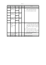
Pulse
instruction
form
CCW
CW
Parameter
setting
Pulse
train
PULS
symb
ol
SIGN
0
Command pulse
+ symbol
Ccw pulse
train
PULS
Cw pulse
train
SIGN
1
Ccw pulse / cw
pulse
Phase a
pulse
train
PULS
Phase b
pulse
train
SIGN
2
2-phase
command
pulse
Summary of Contents for SD300
Page 87: ......
Page 89: ...Chapter 7 Running 7 9 2 Operation l Set the parameter values ...

