7.7 Simple wiring operation in speed control mode
Wiring
•
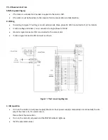
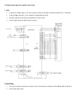
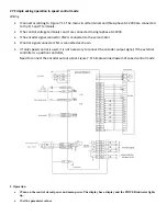
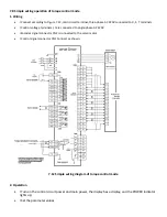
l Connect according to Figure 7.11. The main circuit terminals and three-phase AC 220V are connected
to the R, S and T terminals.
•
l The control voltage terminals r and t are connected to single-phase AC 220V.
•
l The encoder signal connector CN2 is connected to the servo motor.
•
l Control signal connector CN1 is connected as shown.
•
l If only speed control is used, it is not necessary to connect the encoder output signal; if the external
controller is a position controller,
Need to connect the encoder output signal.
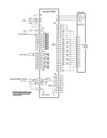
Figure 7.11 Simple wiring diagram of speed control mode
2. Operation
•
l Turn on the control circuit power and main power. The display has a display and the POWER indicator lights
up.
•
l Set the parameter values
Summary of Contents for SD300
Page 87: ......
Page 89: ...Chapter 7 Running 7 9 2 Operation l Set the parameter values ...

