background image

3.3 Set the vehicle geometry 

14 

3.3. Set the vehicle geometry 

Note

: Vehicle dimensions must be accurately measured. Ideally 

measurements should be within one cm / 0.5 inch. The tolerance must 
be /- 5 cm or 2 inches. 

Note

: Ensure the correct dimensions identified by the red lines are 

measured and entered. Incorrect data will affect system performance. 

X30 console 

1.


Select 

Vehicle

 / 

Geometry


2.


Select a vehicle dimension. 

3.


Add or adjust dimensions where required and confirm. 

Universal terminal 

Select 

 from the advanced set-up menu. Refer to Setting UT to 

advanced mode, page 6. 


1.


Select 

Summary of Contents for 1004089-01

Page 1: ...Auto Steering Tuning Guide www topconpa com ...

Page 2: ......

Page 3: ...1K12p2 Copyright Topcon Precision Agriculture All contents in this manual are copyrighted by Topcon All rights reserved The information contained herein may not be used accessed copied stored displayed sold modified published or distributed or otherwise reproduced without express written consent from Topcon www topconpa com ...

Page 4: ......

Page 5: ...re the result of original selection coordination and arrangement by TPA TRADEMARKS ZYNX PROSTEER EAGLE KEE Technologies Topcon Topcon Positioning Systems and Topcon Precision Agriculture are trademarks or registered trademarks of the Topcon Group of companies Microsoft and Windows are trademarks or registered trademarks in the United States and or other countries of Microsoft Corporation Product a...

Page 6: ...RODUCT INCLUDING ANY IMPLIED WARRANTY OR MERCHANTABILITY OR FITNESS FOR ANY PARTICULAR USE OR PURPOSE TPA IS NOT RESPONSIBLE FOR THE OPERATION OF GNSS SATELLITES AND OR AVAILABILITY CONTINUITY ACCURACY OR INTEGRITY OF GNSS SATELLITE SIGNALS LIABILITY LIMIT AND INDEMNITY TPA and its dealers agents and representatives shall not be liable for technical or editorial errors or omissions contained herei...

Page 7: ...se Terms and Conditions Service Information Service assistance can be provided by contacting your local TPA Authorized Dealer Communications Regulation Information FCC Compliance Statement USA This equipment has been tested and found to comply with the limits for a Class A digital device pursuant to Part 15 of the FCC Rules Operation of this equipment in a residential area is likely to cause harmf...

Page 8: ... the equipment to another circuit that is not linked to the radio To reduce potential interference operate the equipment at the lowest gain level that will allow successful communication If necessary contact your nearest Topcon Precision Agriculture dealer for assistance Note Changes or modifications to this product not authorized by TOPCON Precision Agriculture could void the EMC compliance and n...

Page 9: ...e correct location and can be read Replace any safety signs that cannot be read or are missing Replacement safety signs are available from your dealer Operator Safety WARNING It is YOUR responsibility to read and understand the safety sections in this book before operating this vehicle Remember that YOU are the key to safety Good safety practices not only protect you but also the people around you...

Page 10: ... of at least 20 cm 7 8 inches between people and any radiating antenna Keep a distance of at least 20 cm between transmitting antennas WARNING Products using cellular modem or an RTK base station can transmit radio frequency energy Check with your dealer This device is designed to operate with TPA approved antennas Discuss with your dealer Preparation for Operation Read and understand this manual ...

Page 11: ...fety Information Operator Alertness and Responsibility The console helps the operator to steer the vehicle but the operator remains in charge and must be alert and in complete control of the vehicle at all times The operator is ultimately responsible for safe operation of this equipment It is essential that safety requirements are met when operating the console and any of its components All operat...

Page 12: ...proper distance Steering needs to be disengaged for manual control if an obstacle appears in the path or the vehicle moves away from the wayline On Off and Manual Control WARNING Ensure the steering switch is Off to prevent unintentional engagement of the assisted steering When repairing or maintaining the vehicle implement ensure the vehicle CANNOT be moved Disengage steering apply brakes and rem...

Page 13: ...nes When using the portable reference station make sure that the tripod is securely mounted To Get the Best Out of the Product Back up data regularly The console has large but limited storage capacity Use the Diagnostics Mini view to view capacity available A warning screen displays if storage is reaching its limit Be aware of file format compatibility Discuss compatible formats with the dealer To...

Page 14: ...icle geometry 14 3 4 Select the steering controller 16 3 5 Steering calibrations 18 3 5 1 Accessing the calibration screen 18 3 5 2 Compass calibration 20 3 5 3 Wheel angle sensor calibration with AES 25 and Fendt FSC 20 3 5 4 Wheel angle sensor calibration without AES 25 22 3 5 5 Hydraulic system calibration 23 3 5 6 Mounting bias calibration 25 Default Tuning Values 29 Chapter 4 4 1 AES 25 with ...

Page 15: ...factors can affect the performance of the steering system Tyre size and number Implement size shape and loading Vehicle speed Terrain and soil condition Tuning the vehicle is a real world application that is best performed in actual working conditions For example On soft ground with the implement fitted and engaged in work Hydraulic fans running if it is a seeder For self propelled sprayers have b...

Page 16: ...ollow the instructions supplied for the X30 console if X14 instructions are not supplied separately Note If you are using an ISO UT console the advanced tuning settings are not accessible The AES 25 wheel angle sensor is not supported for ISO UT Contact Topcon technical support for assistance ...

Page 17: ...2 1 X14 console 2 1 1 Setup and operation screens The X14 console has two main screens that are used during tuning the Operation screen and the Setup screen Use the highlighted buttons to switch between the screens 2 1 2 Steering options menu The steering tuning settings are accessed using the steering options menu ...

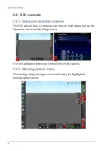
Page 18: ...X30 console has two main screens that are used during tuning the Operation screen and the Setup screen Use the highlighted buttons to switch between the screens 2 2 2 Steering options menu The steering tuning settings are accessed using the highlighted steering options menu ...

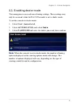
Page 19: ... set the console to dealer mode 1 Select User Access Level 2 Select ACCESS LEVEL and select Dealer 3 Select PASSWORD and enter the dealer password then confirm Note When the console is set to dealer mode the number of tuning options displayed on the steering options menu will change The number of options displayed will vary depending on the type of steering controller and its configuration ...

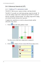
Page 20: ...To access the settings required for vehicle tuning the ISO UT terminal must be switched to advanced mode The settings required for tuning are selected from the advanced set up menu Complete the steps below to switch to advanced mode and the advanced set up menu 1 Select from the basic guidance mode The first screen of the basic setup menu is displayed 2 Select to display the next menu of the basic...

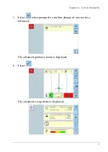
Page 21: ...Chapter 2 Console Navigation 7 3 Select when prompted to confirm change of user mode to advanced The advanced guidance menu is displayed 4 Select The advanced set up menu is displayed ...

Page 22: ...2 4 Universal terminal UT 8 ...

Page 23: ...e page 12 3 Set the vehicle geometry See Set the vehicle geometry page 14 4 Select the steering controller See Select the steering controller page 16 5 Perform a compass calibration See Compass calibration page 20 6 Perform a wheel angle sensor calibration if a wheel angle sensor is fitted See Wheel angle sensor calibration with AES 25 and Fendt FSC page 20 or Wheel angle sensor calibration withou...

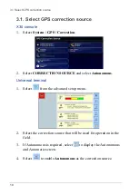
Page 24: ...Select CORRECTION SOURCE and select Autonomous Universal terminal 1 Select from the advanced setup menu 2 Select the correction source that will be used for operation in the field 3 If Autonomous is required select to display the Autonomous and Automatic screen 4 Select to enable Autonomous as the correction source ...

Page 25: ...Chapter 3 Tuning Preparation 11 ...

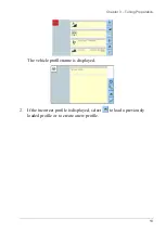
Page 26: ... The current vehicle profile is displayed with a green tick next to it 2 If the incorrect profile is displayed select another profile from the list or select Vehicle New to create a new profile Universal terminal Select from the advanced set up menu Refer to Setting UT to advanced mode page 6 1 Select ...

Page 27: ...Chapter 3 Tuning Preparation 13 The vehicle profile name is displayed 2 If the incorrect profile is displayed select to load a previously loaded profile or to create a new profile ...

Page 28: ...e within 5 cm or 2 inches Note Ensure the correct dimensions identified by the red lines are measured and entered Incorrect data will affect system performance X30 console 1 Select Vehicle Geometry 2 Select a vehicle dimension 3 Add or adjust dimensions where required and confirm Universal terminal Select from the advanced set up menu Refer to Setting UT to advanced mode page 6 1 Select ...

Page 29: ...Chapter 3 Tuning Preparation 15 2 Select The vehicle geometry settings are displayed 3 To add or adjust a vehicle dimension select a dimension ...

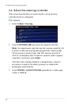
Page 30: ...t the specific steering controller if it is listed so that auto steering settings match the vehicle profile If the system is factory Fendt then FSC must be selected If AES 25 is fitted then AES 25 must be selected If the required controller is not listed select Other Note that if the steering controller is changed later it may be necessary to return to the vehicle geometry to confirm the dimension...

Page 31: ...er 3 Tuning Preparation 17 Universal terminal 1 Select from the vehicle geometry menu 2 Select Steering Mode Select the required controller 3 Select Wheel Angle Sensor if installed Uncheck the box to enable ...

Page 32: ...he vehicle s position and control the vehicle s steering system For this to work properly the system needs to be calibrated for the individual vehicle The steering calibrations must be carried out before the tuning process is commenced This should be done every time tuning is carried out regardless of the calibration state 3 5 1 Accessing the calibration screen X30 console 1 Select Steering Option...

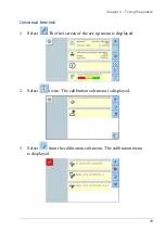
Page 33: ... Preparation 19 Universal terminal 1 Select The first screen of the set up menu is displayed 2 Select twice The calibration sub menu is displayed 3 Select from the calibration sub menu The calibration menu is displayed ...

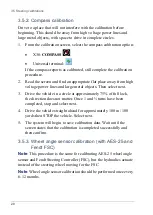
Page 34: ...hen select next 3 Drive the vehicle in a circle at approximately 75 of full lock the direction does not matter Once 1 and turns have been completed stop and select next 4 Drive the vehicle straight ahead for approximately 100 m 100 yards then STOP the vehicle Select next 5 The system will begin to save calibration data Wait until the screen states that the calibration is completed successfully and...

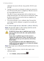
Page 35: ...forward to start the procedure The wheel angle sensor calibration should be completed at approximately 2 kph or 1 2 mph Select next The AES 25 motor will move full lock to the left and hold the wheels in the full lock left position until the vehicle has moved just over a quarter of a turn When the left side value has been calibrated the console will emit a beep and the AES 25 motor will stop 3 Sel...

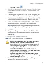
Page 36: ...ed successfully and then confirm 3 5 4 Wheel angle sensor calibration without AES 25 Note This procedure applies to other steering controllers not the AES 25 with wheel angle sensor support WARNING Ensure there is sufficient space for the tractor to drive forward in the center position before proceeding Ensure there is sufficient space for the tractor to complete the full maneuver before selecting...

Page 37: ...formance 6 Select next 7 The system will begin to save calibration data Wait until the screen states that the calibration is completed successfully and then confirm 3 5 5 Hydraulic system calibration Note This is only applicable to ACU 1 installations WARNING During hydraulic calibration the vehicle will automatically move the front axle wheels progressively to the left position and then progressi...

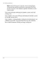
Page 38: ...shold set in the vehicle profile The system will begin calibrating the hydraulic system for the left steering valve Once complete the system will begin calibrating the hydraulic system for the right steering valve Once complete a message displays stating that steering hydraulics are calibrated successfully The left and right steering valve minimum Pulse Width Modulation PWM percentage is displayed...

Page 39: ...visable to still perform a mounting bias calibration when using Autonomous as the Correction Source System GPS Correction even though the console reports that it is not required Mounting bias calibration is performed in a clear flat area well away from obstacles If the mounting of the receiver is not quite level this calibration will adjust for the actual position WARNING Ensure the vehicle has su...

Page 40: ...peration screen to auto steer on the wayline The icon will turn green an audible tone will sound and an engage message will flash on screen to indicate the auto steering has engaged If steering does not engage when Auto Steer Engage is selected the steering status box will appear 6 Address any of the issues with red indicators before proceeding with the mounting bias calibration procedure 7 Drive ...

Page 41: ...e will increase When the Calibration Progress bar reaches 100 this indicates the system has enough data for the second stage of the calibration and the mounting bias calibration is paused at this point 16 Proceed to cross the B waypoint and wait until the screen reports saving calibration and calibration successful before steering off course 17 Stop the vehicle Mounting bias has been successfully ...

Page 42: ...3 5 Steering calibrations 28 ...

Page 43: ... 30 30 30 10 Max Steering Angle 30 30 25 25 Smoothing Radius for Curved Lines 7 7 7 7 Sensitivity Adjustment 100 100 100 100 Deadband Adjustment 20 20 20 20 Disengage Threshold 15 15 15 15 Advanced Steering Tuning pTime 0 95 0 75 0 85 0 90 pTime off 1 15 0 95 1 05 1 10 DGain N A N A N A N A PGain N A N A N A N A Wheel Angle Sensor Tuning Low Speed Differential Gain 2 2 2 2 High Speed Differential ...

Page 44: ... 60 40 70 40 50 40 Approach Aggressiveness 20 30 30 30 10 10 Max Steering Angle 30 30 30 25 25 25 Smoothing Radius for Curved Lines 7 7 7 7 7 7 Sensitivity Adjustment 100 100 100 100 100 100 Deadband Adjustment 10 20 20 20 20 20 Disengage Threshold 15 15 15 15 15 15 Advanced Steering Tuning pTime 0 9 1 0 1 0 1 0 1 0 1 0 pTime off 1 3 1 3 1 3 1 3 1 3 1 3 DGain N A N A N A N A N A 100 PGain N A N A ...

Page 45: ...g pTime 0 9 1 0 85 1 1 0 95 pTime off 1 1 1 2 0 95 1 1 1 1 1 05 Max PWM N A 70 70 70 60 N A WAS Gain N A 70 100 100 120 N A Wheel Angle Sensor Tuning Left min Auto Calibration Right min Auto Calibration Note Low speed figures refer to 3 4 km h and high speed to 34 km h Note Excluding AES 25 and ACU 1 all other steering controllers have tuning values set by default Only pTime and Aggressiveness val...

Page 46: ...4 3 ACU 1 steering ECU 32 ...

Page 47: ...oach and follow the AB line without excessive deviation as shown below A B Small deviations from the line are normal but large deviations should be prevented by correct tuning 1 Set the tuning settings to the default settings listed in the previous chapter before tuning is attempted 2 Analyze the steering behavior and adjust the appropriate settings described in this chapter Each vehicle will beha...

Page 48: ...terminal Steering controller 1 Select from the vehicle geometry screen The Steering tuning settings are displayed on the steering control settings page Steering response 2 Select from the advanced setup screen The vehicle sub menu will be displayed 3 Select to display the Line Acquisition Steering Response and Online Steering Response settings ...

Page 49: ...ome unstable Maximum steering angle Limits the angle of turn to stay within the limits of the vehicle s safe capability Smoothing radius for curved waylines Sets how tight or loose the auto steering will adhere to curved waylines AES 25 sensitivity adjustment Adjusts the responsiveness of the AES 25 when following the AB line AES 25 deadband adjustment Allows you to adjust the minimum wheel reacti...

Page 50: ...mall adjustment to this value makes a big difference The Ptime value is in seconds Ptime off Sets the prediction time look ahead of the steering controller The prediction time sets how far ahead the vehicle will focus when it is not on the guideline It is used when the vehicle s cross track error is more than 50 cm and 10 deg heading A small adjustment to this value makes a big difference DGain On...

Page 51: ...Chapter 5 Tuning Procedure 37 Steering tuning settings Max PWM The maximum speed at which the system will operate the hydraulic valve WAS Gain Adjusts the influence of the wheel angle sensor response ...

Page 52: ... error the faster the AES 25 will respond to reduce the error Max RPM Determines the maximum speed at which the AES 25 can rotate when the steering is engaged This figure is a limiter Having this value too high can allow rapid changes in the vehicle direction resulting in equipment damage Setting this value too low can make the vehicle too slow to respond and cause the vehicle to overshoot the lin...

Page 53: ...ystem Note Low speed settings relate to a speed of 3 4 km h and high speed settings relate to the speed that matches the highest speed planned approximately 34km h however the vehicle does not need to be driven at these speeds to adjust the settings The actual gain figures used by the system vary with the speed at which the vehicle is travelling ...

Page 54: ...e operates and steers at the required operational speed in the desired conditions with the desired results Note Tune an AES 25 system to a reasonable operation first before turning on the WAS and retuning with the advanced features The advanced tuning will only improve a system that is steering correctly in the first place and will not fix any initial setup or tuning issues In a lot of cases if th...

Page 55: ...oose steering components Inspect steering system for worn or loose steering components replace or repair GPS receiver has a loose fitting or is fitted incorrectly Check receiver mounting is secure and correctly fitted Aggressive snaking motion The vehicle appears to be continually moving back and forth when looking over the front nose of the vehicle Although a lot of motion is observed the cross t...

Page 56: ...ow Increase Approach Aggressiveness setting pTime Off setting too low Increase pTime Off setting GPS receiver has a loose fitting or is fitted incorrectly Check receiver mounting is secure and correctly fitted Wheel angle sensor calibration corrupted Re calibrate wheel angle sensor Aggressive line acquisition The autosteering overshoots the line and continues to overcompensate during acquisition R...

Page 57: ...ster vehicle type Load correct vehicle type DGain setting not used when tuning Adjust DGain setting PGain not used during tuning Adjust PGain setting Auto steering keeps disengaging The auto steering keeps disengaging and all system settings appear ok AES 25 Disengage Threshold setting too low Increase AES 25 Disengage Threshold setting Binding or worn steering components Inspect steering system f...

Page 58: ...Precision Agriculture Avenida de la Industria 35 Tres Cantos 28760 Spain Phone 34 91 804 92 31 Fax 34 91 803 14 15 Topcon Positioning Systems Inc 7400 National Drive Livermore CA 94551 USA Phone 925 245 8300 Fax 925 245 8599 Topcon Corporation 75 1 Hasunuma cho Itabashi ku Tokyo 174 8580 Japan Phone 81 3 5994 0671 Fax 81 3 5994 0672 Topcon Precision Agriculture All rights reserved Specifications s...

Reviews: