Managing the Radio Modem
P/N 7010-1004
3-17
In free channel scan mode, the Base radio modem will regularly
scan the current operating frequency to determine the degree of a
radio noise (interference). Should the level of noise on the current
operating frequency be greater than the threshold specified in this
field, the transmitter will stop broadcasting and switch to the next
frequency. It can be
Off
(default), Master, Slave, Repeater,
Repeater, or Slave + Repeater.
•
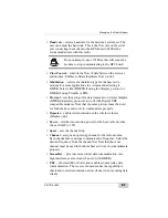
Protocol
- selects a modulation type for the base radio modem
from
Satel 3AS
(default)
,
PacCrest 4FSK, PacCrest GMSK w/
EOT.
•
Satel FEC
- (Forward Error Correction) enable to maximize data
communication. The rover radio modem has the capability to
check and correct transmission errors (if any) in an incoming data
stream.
•
Spacing, kHz
- shows the channel step. It can be 12.5, 20, 25.
• Pressing the
Refresh
button
renews the list.
• Pressing the
Import
button
imports settings from a file.
• Pressing the
Export
button
saves settings in a file.
• Pressing the
Load
button
writes new setting into the modem.
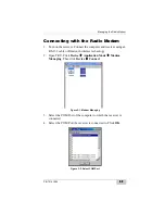
4. When finished configuring the radio modem, always disconnect
from TRU before exiting to prevent conflicts with serial port
management.
NOTICE
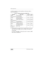
To properly communicate, the Base and Rover
radios require the same settings for Current
Frequency, Signal Threshold Level, FCS, Spacing,
and so on.
This page is intentionally left blank
Summary of Contents for GR-5
Page 1: ... PERATORlS ANUAL ...
Page 2: ......
Page 4: ...ECO 4074 ...
Page 9: ...Table of Contents P N 7010 1004 v WEEE Directive C 2 Appendix D Warranty Terms D 1 Index ...
Page 10: ...Table of Contents GR 5 Operator s Manual Notes vi ...
Page 16: ...Preface GR 5 Operator s Manual Notes xii ...
Page 18: ...Introduction GR 5 Operator s Manual 1 2 Figure 1 1 GR 5 Receiver ...
Page 44: ...Introduction GR 5 Operator s Manual Notes 1 28 ...
Page 99: ...Configuring the Receiver Using TRU P N 7010 1004 3 27 Figure 3 24 Add New Message ...
Page 121: ...MINTER Configuration P N 7010 1004 3 49 Figure 3 42 MINTER Tab ...
Page 122: ...GR 5 Configuration GR 5 Operator s Manual 3 50 ...
Page 170: ...Troubleshooting GR 5 Operator s Manual Notes 6 12 ...
Page 188: ...GR 5 Operator s Manual Notes A 18 ...
Page 192: ...GR 5 Operator s Manual Notes B 4 ...
Page 196: ...GR 5 Operator s Manual Notes D 2 ...
Page 201: ......


