MC-
X
1 Connectivity and Configuration
Assigning GR-i3 Vibration Mount to Auxiliary
8
Excavator Indicate System
P/N: 1022461-01
Assigning GR-i3 Vibration Mount to Auxiliary
The Main GR-i3 Vibration Mount must be disconnected from the system in order to assign an
Auxiliary (AUX) antenna.
1. Open 3D-MC to create a machine builder file (if one has not already been created), and select
MC-X1
from the
Position input
drop-down menu. If a machine builder has already been
configured, make sure MC-X1 is selected as the Position Input.
2. Navigate to the end of the machine builder, and tap
Finish
.
3. Ensure the correct machine file is selected on the
Machine files
page, and tap
OK
. Now, your
.mx3 is deployed, and the necessary sensors will populate in the MC-X Machine Control Gateway
Sensors
menu.
4. Open MCXCONFIG.
5. Disconnect the CAN cable from the bottom of the Main GR-i3 Vibration Mount on the Left side of
the machine.
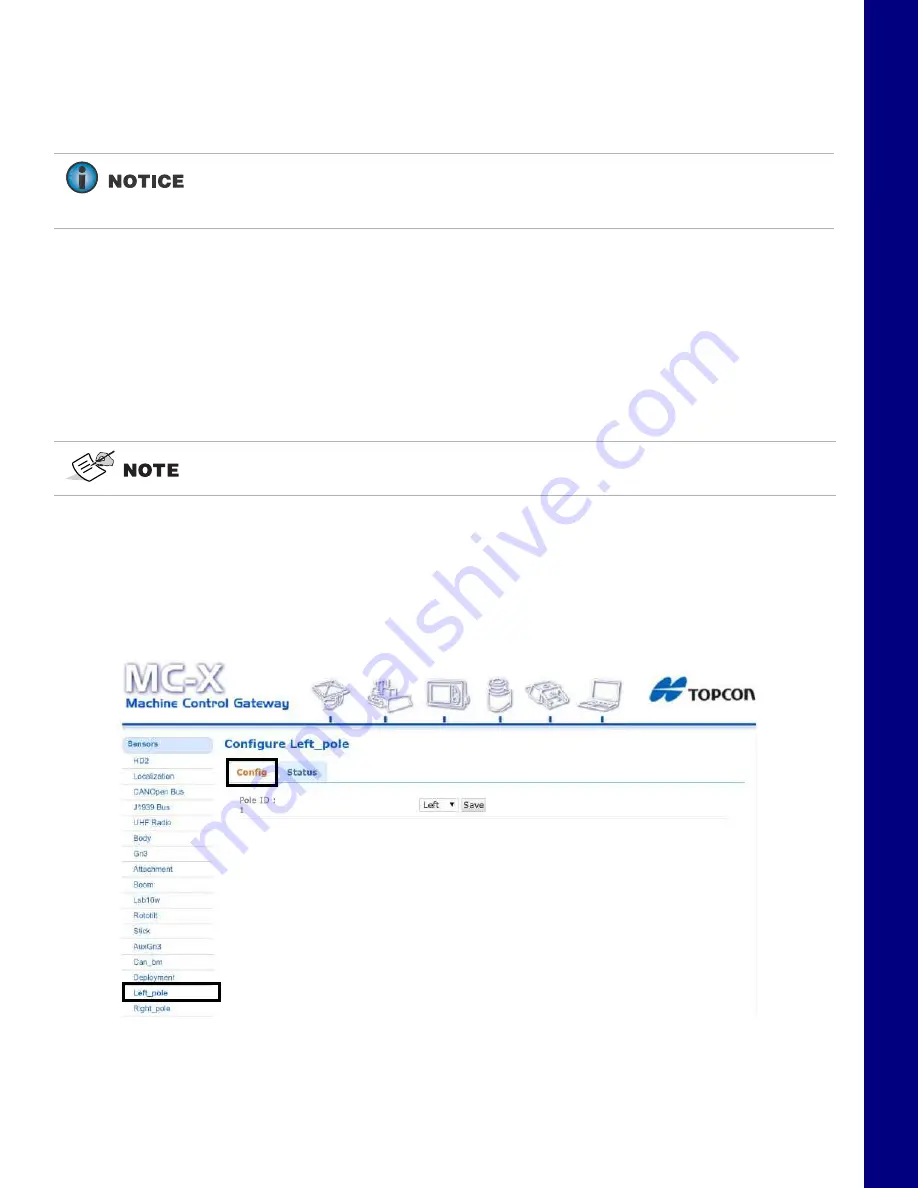
6. From the menus on the left of the screen, click
Sensors > Left_pole
, and then click the
Config
tab..
Figure 12. Settings - Left Pole - Config Tab
7. Select
Right
from the drop-down menu (Figure 13).
If
Left Pole
,
Right Pole
,
GRi3
, or
AuxGRi3
do not populate in the MC-X Machine
Control Gateway
Sensors
menu, 3DMC must deploy a machine file with MC-X1 as
Position input.
An .mx3 file that is active in 3D-MC is considered the “deployment”.


