Calibration
Calibrating the LS-B10W
59
Excavator Indicate System
P/N: 1022461-01
Calibrating the L
S
-B10W
To calibrate the LS-B10W Laser Receiver, determine the position of the receiver on the stick. After
calibrating the sensor, 3D-MC will determine the angle of the LS-B10W to the stick center line.
1. Position the machine on a stable surface free of obstructions, and rotate the body to 0.0° roll.
2. Orient the stick so that the LS-B10W is positioned vertically.
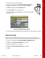
3. On the GX Series display, tap the
Power Button
Control
Machine setup
. Select the
applicable machine file for the job, and tap
Edit
.
4. Tap
Next
to navigate to the
Laser Receiver (LSB10W)
screen.
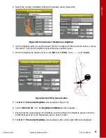
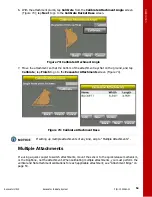
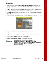
5. Enter the following measurements for the LS-B10W (Figure 79).
•
Depth to center of stick
– enter the measurement for the distance between the middle of
the stick to the light cells on the LS-B10W.
•
From bucket pivot
– enter the measurement for the distance from the along the projected
line between the bucket pivot and stick pivot at the point where the LS-B10W is perpendicular
to the projected line (Figure 79).
•
Left of pivot line
– enter the measurement for the distance between the mark on the LS-
B10W and the pivot line. If right of pivot line, use a negative value.
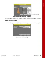
6. Make sure the LS-B10W Laser Receiver is vertical, and then tap
Calibrate
to determine the
angle between the stick and the LS-B10W (Figure 79).
Figure 79: LS-B10W Laser Receiver Measurements
If the stick sensor is replaced with a new tilt sensor, you must recalibrate the
LS-B10W Laser Receiver.
To test the LS-B10W calibration, see “LS-B10W Test” on page 66.


