Troubleshooting
Motorgrader System Five Operator’s Manual
7-12
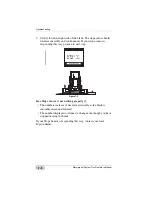
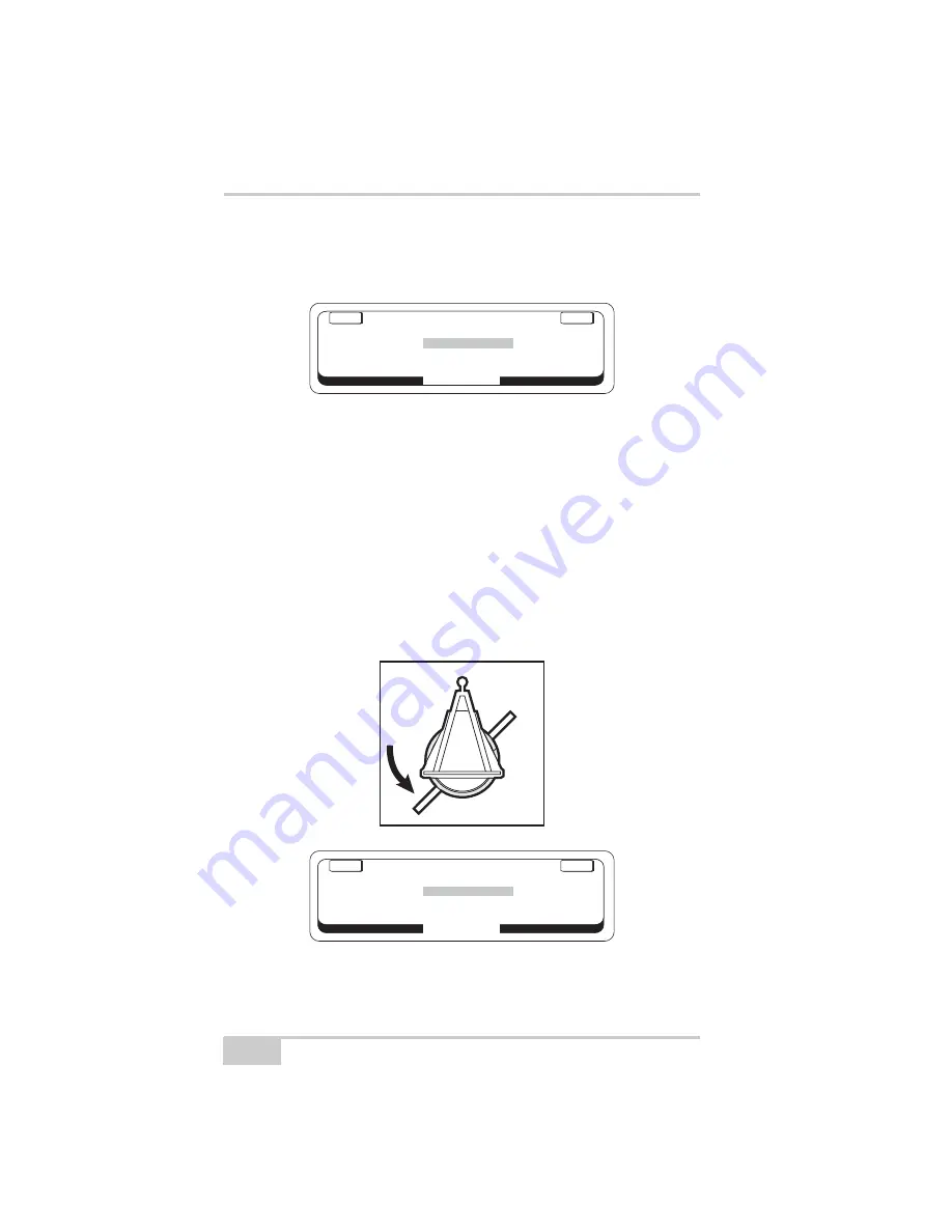
3. The value next to rotation should display 0 degrees. If it does not
read 0 degrees, recalibrate the Rotation Sensor in its current
position and re-enter the System Test Mode.
Figure 7-14.
4. Proceed by rotating the circle counterclockwise continuously and
smoothly to about a 45 degree angle (the right side of the blade
should be approximately 1 foot from the front tire.)
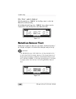
The value next to "Rotation" should display the increase from 0
degrees to 45 degrees in a smooth transition:
• If the numbers jump erratically as the circle is being rotated,
then the Rotation Sensor is not working properly.
• If the numbers do not change, as the circle is being rotated,
remove the Rotation Sensor and check to make sure the pin
has not fallen out.
Figure 7-15.
ENTER
EXIT
KNOB
VALVE
LASER
SONIC
KNOB
VALVE
LASER
SONIC
MAINFALL
ROTATION
0°
SLOPE
SYSTEM TEST
ROTATE BLADE 45°...
ENTER
EXIT
KNOB
VALVE
LASER
SONIC
KNOB
VALVE
LASER
SONIC
MAINFALL
ROTATION
45°
SLOPE
SYSTEM TEST
45°
Summary of Contents for Motorgrader
Page 1: ...OTORGRADER 3YSTEM IVE4 ONTROL OX PERATORlS ANUAL...
Page 2: ......
Page 4: ...ECO 2955...
Page 8: ...Table of Contents Motorgrader System Five Operator s Manual Notes iv...
Page 22: ...System Overview Motorgrader System Five Operator s Manual Notes 1 12...
Page 58: ...Operation Motorgrader System Five Operator s Manual Notes 2 36...
Page 168: ...Safety Information Motorgrader System Five Operator s Manual Notes A 4...
Page 171: ......


