background image


TOPCON OS SERIES TOTAL STATION AND MAGNET FIELD 

OS Series Resection Setup Quick Guide 

This  Quick  Guide  is  to  show  you  how  to  setup  and  orientate  the  Topcon  OS  Series  Total 
Station using the Resection Method. 

Principles of a 

Resection

Resection  is  used  to  determine  the  coordinates of  an  instrument  position  (station  point)  by 
performing multiple measurements of points whose coordinate values are known.   

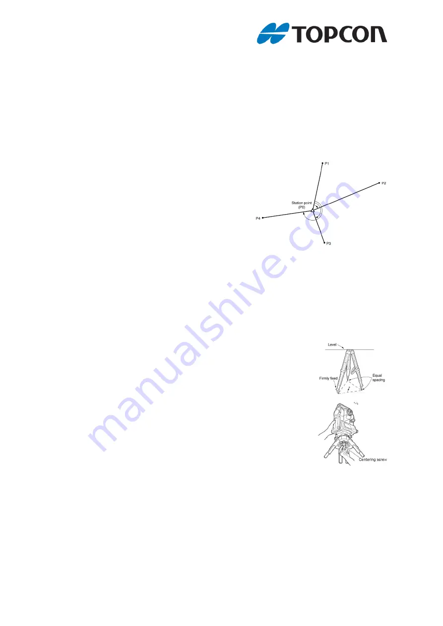
We need a minimum of two known points to perform a 
resection,  but  the  more  points  that  are  known  and 
used,  the  higher  the  precision  of  the  calculated 
instrument position.  We would always recommend a 
minimum of three known points to be used. 

In this diagram you can see the Instrument is setup at 
P0 and we have known points at positions P1 to P4. 

We are going to use P1, P2 and P3 for our resection. 


It is important to make sure that the battery is seated in the instrument prior to setting 
the Total Station up as the weight of the battery will affect the level of the instrument. 

Step One: Positioning the Instrument 


1)  Locate  a  position  where  you  can  observe  at  least  two  known 

control points. 
Make sure the Tripod legs are spaced at equal intervals and the 
Tripod head is roughly level. 
Make sure the Tripod feet are firmly fixed in the ground.


Tip:  Set  the  height  of  the  Tripod  head  at  mid  chest  height  to 
ensure the telescope of the instrument is at eyelevel. 
 

2)  Place the Instrument on the Tripod head. 

Supporting  it  with  one  hand,  tighten  the  centring  screw  on  the 
bottom of the unit to make sure it is secured to the Tripod. 


Summary of Contents for OS Series

Page 1: ... can see the Instrument is setup at P0 and we have known points at positions P1 to P4 We are going to use P1 P2 and P3 for our resection It is important to make sure that the battery is seated in the instrument prior to setting the Total Station up as the weight of the battery will affect the level of the instrument Step One Positioning the Instrument 1 Locate a position where you can observe at l...

Page 2: ...icates the bubble in the circular level 3 Centre in the Circular level 4 Turn the Instrument until the telescope is parallel To a line between levelling foot screws A and B 5 Set the tilt angle to 0 using foot screws A and B for the X direction and levelling screw C for the y direction Remember Fingers and Thumbs Always turn A and B in opposite directions to half the error on each foot screw 6 Pre...

Page 3: ...tion is setup on In this case P0 There is no need to enter the Height of the Instrument HI Tap the Next Icon 4 MAGNET Field now asks you to specify your first control point in this case P1 You can select the point from the map or list icons or manually enter the ID If the point is not in the Database you will be taken to the Add Point Screen Enter your Prism Height 0m in this example Sight the Ins...

Page 4: ...ou to the same screen we saw in step 5 we have selected known point P3 Don t forget pole height and tapped the Measure icon 8 MAGNET Field returns us to our results screen and we can now check our residuals in this case EN and Z values are all zero which is a perfect result In the field an error of a few mm is perfectly normal We can check the individual results in the table and if needed we can r...

Reviews: