background image

18

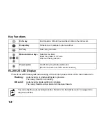
Key Functions

RL-200 2S LED Display

There is an LED that signals auto-leveling of the control panel screen of the main instrument.

Flashing :

Auto-leveling or grade setting is in process.
The rotary head is not rotating.

ON solid :

Auto-leveling grade setting is complete.
The rotary head is active and emits the laser beam.

Enter key

End Operation of Data Input and Sends data to the instrument.

Escape key

Cancels input or escape to previous status.

X/Y key

Sets each grade axis.

Menu and arrow keys

Selects menu items.
Inputs the grades of X Y axis.
Sets the masking direction.

Power switch

On/Off of the RL-200 2S and RC-400.
(RC-400 has auto-cut off 60 seconds function)

You can stop the auto-levelling function. Refer to “4) Sensitivity Level” on page 34 to 
stop the function.

Summary of Contents for RL-200 1S

Page 1: ...INSTRUCTION MANUAL ROTATING LASER RL 200 2S 31492 90030 ESC MENU ENT X Y...

Page 2: ......

Page 3: ...ent against shock When transporting the instrument provide some protection to minimize risk of shock Heavy shocks may affect beam accuracy Sudden changes of temperature A sudden change in temperature...

Page 4: ...ain text Definition of Indication WARNING Ignoring this indication and making an operation error could possibly result in death or serious injury to the operator CAUTION Ignoring this indication and m...

Page 5: ...occur When securing the instrument in the carrying case make sure that all catches including the side catches are closed Failure to do so could result in the instrument falling out while being carrie...

Page 6: ...re could result Do not use batteries other than those designated An explosion could occur or abnormal heat generated leading to fire Do not place articles such as clothing on the battery charger while...

Page 7: ...ape or equivalent to the terminals Otherwise shorting could occur resulting in fire or burns Do not use batteries or the battery charger if wet Resultant shorting could lead to fire or burns Do not co...

Page 8: ...ted Failure to tighten the screws could result in the tripod collapsing causing injury Do not carry the tripod with the tripod shoes pointed at other persons A person could be injured if struck by the...

Page 9: ...sequential damage and loss of profits by any disaster an earthquake storms floods etc A fire accident or an act of a third party and or a usage any other usual conditions The manufacturer or its repre...

Page 10: ...ible laser beam during operation This product is manufactured and sold in accordance with Performance Standards for Light Emitting Products FDA BRH 21 CFR 1040 or Radiation Safety of Laser Products Eq...

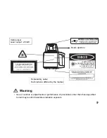
Page 11: ...than those specified herein may result in hazardous radiation exposure Visible laser Laser output 2 5mW Beam aperture Explanatory Label Each label is differed by the market CLASS a LASER PRODUCT AVOI...

Page 12: ...ermanent eye damage Sight targets so that the laser beam does not stray from them Caution Perform checks at start of work and periodic checks and adjustments with the laser beam emitted under normal c...

Page 13: ...oduct Hazardous protection procedures read Laser Safety Information Requisite protective gear read Laser Safety Information Accident reporting procedures stipulate procedures beforehand for transporti...

Page 14: ...ype 1 Instrument 1pc 2 Remote controller RC 400 1pc 3 Level Sensor LS 80L 1pc 4 Level Sensor Holder Model 6 1pc 5 Battery holder DB 75C 1pc 6 Ni MH battery pack BT 67Q 1set 7 AC DC converter AD 11 1pc...

Page 15: ...System Components 12 Contents 13 Nomenclature 15 Sample Display 17 Key Functions 18 RL 200 2S LED Display 18 Basic Operation 19 Preparation and Functions 20 Power Source 20 Setting Up Instrument 20 RC...

Page 16: ...tteries on the Instrument 37 How to Replace the RC 400 Batteries 41 Check and Adjusting 42 Horizontal Calibration 42 Horizontal Rotation Cone Error 46 Grade Setting Error 47 Storage Precautions 49 Sta...

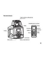
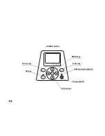
Page 17: ...NU ENT X Y Rotary head Laser emitting window Beam aperture RC 400 Remote Controller Handle Battery holder Control panel Battery compartment lock Display Escape key Enter key X Y key Power switch Arrow...

Page 18: ...16 ESC MENU ENT X Y Escape key Enter key X Y key Power switch Arrow keys MENU key Control panel Auto leveling indicator...

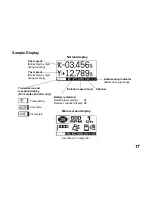
Page 19: ...Blinks during leveling Transmission and reception display On remote controller only Battery remaining Rotating laser display RL Remote controller display RC Transmitting Complete Incomplete Channel Y...

Page 20: ...ad is active and emits the laser beam Enter key End Operation of Data Input and Sends data to the instrument Escape key Cancels input or escape to previous status X Y key Sets each grade axis Menu and...

Page 21: ...nsor If high precision detection is desired select that setting on the level sensor 4 Check the rotating beam elevation using the level sensor Normal precision mode High precision mode Level sensor Hi...

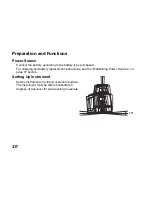
Page 22: ...rchased For charging and battery replacement instructions see the Maintaining Power Sources on page 37 section Setting Up Instrument Set the instrument on a tripod or smooth surface The instrument mus...

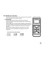
Page 23: ...e instrument and the remote controller When the ENT key is pressed entered information is transmitted from the remote controller to the instrument When information is received by the instrument it sen...

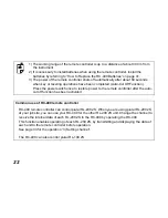
Page 24: ...once to restore power to the remote controller after the auto cut off function has been activated Common use of RC 400 remote controller RC 400 remote controller can control plural RL 200 2S When you...

Page 25: ...n such case please turn the power on once again Always turn off the power for the RC 400 before turning off the power for the instrument after the operation If you forget to turn off the power for the...

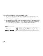
Page 26: ...will be displayed 2 When the search is finished the available channel and serial number of the instrument will be displayed If more than one channel is displayed use the arrow key up down to position...

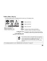
Page 27: ...evel display will not change Once the power is turned off the battery remaining display will reset Battery remaining display Rotating laser display RL Remote controller display RC RL BATTERY LOW or RC...

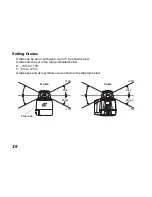
Page 28: ...both axes X and Y as shown below Grades can be set in the range indicated below X 10 to 10 Y 5 to 25 Grade axes and axis symbols are as shown in the diagram below ESC MENU ENT X Y 10 X axis Y axis 10...

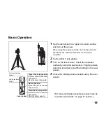
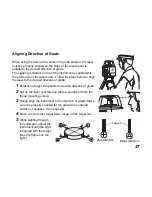
Page 29: ...ion of grade 1 Establish a target line parallel to desired direction of grade 2 Set up the laser over this line drop a plumb bob from the tripod mounting screw 3 Rough align the instrument to the dire...

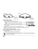
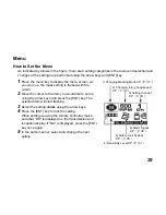
Page 30: ...essing the arrow keys Right or Left 4 Increase or decrease the number by pressing the arrow keys Up or Down 5 Press the ENT key to finish input When setting up using the remote controller Confirm the...

Page 31: ...using the arrow keys and press the ENT key The selected item will start flashing 3 Select the setting details using the arrow keys 4 Press the ENT key to lock the setting When setting up using the rem...

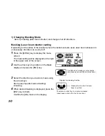
Page 32: ...he upper side of the screen 2 Use the arrow keys to position on the Mask display and press the ENT key 3 Select the direction you desire to mask using the arrow keys Each press repeats mask activating...

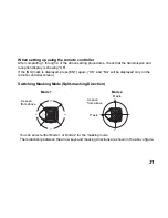
Page 33: ...f the NG mark is displayed press ENT again OK and NG will be displayed only on the remote controller screen Switching Masking Mode Split masking Direction Mode 1 Mode 2 As seen from above As seen from...

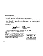
Page 34: ...ion display If NG is displayed press the ENT key once again Sample display 2 How to change the rotary head speed 300 600 900 R P M The rotary head speed can be set to 300 600 or 900 R P M Press the me...

Page 35: ...CH Refer to How to Set the Menu on page 29 and press the ENT key to lock entry 2 Search for the channels available on active or standby RL 200 2S When the search is completed searched channels will be...

Page 36: ...eration of the operational precision Two sensitivity levels can be set large and small vibrations Manual setting will stop the auto leveling function Do not use the manual setting for sensitivity leve...

Page 37: ...e when auto leveling is functioning and laser beam is being emitted through for example unnecessary contact by the user the auto leveling function will automatically stop to protect operational precis...

Page 38: ...n used with the Topcon level sensor the RL 200 2S can communicate alarm signals directly to the sensor This helps enable the user to be completely aware of potential problems before they can become se...

Page 39: ...ment and turn the battery cover knob to LOCK Charging 1 Plug the AC DC converter AD 11 into the DB 75C battery holder 2 Plug the converter power cord into the appropriate AC outlet 3 When charging is...

Page 40: ...hydride batteries Recharging should be performed in a room temperature ranging from 10 C to 40 C Always use the AC DC converter provided with the product 1 The Ni MH BT 67Q rechargeable battery can b...

Page 41: ...he battery source will discharge when stored and should be checked before using with instrument 3 Be sure to charge stored battery source every 3 or 6 months and store in a place at 30 C or below If y...

Page 42: ...ry cover knob to OPEN 2 Remove the old batteries and replace with new batteries 4 D size dry cell batteries matching and as shown in the figure 3 Replace the battery cover and turn the knob to LOCK Re...

Page 43: ...to slide the cover in 2 direction The cover does not move but it will be open 2 Remove the old batteries and replace with new batteries three AA batteries matching and as shown in the figure 3 Replac...

Page 44: ...direction shown in the right figure Y axis facing the wall 2 While pressing the X or Y key turn on the power switch 3 The flashing axis is the selected one Select the axis to check using the arrow ke...

Page 45: ...r the level sensor and press the detective precision switch to select the high detection mode 7 Check the position of the laser beam Y on the wall Move the sensor up or down until the LCD indicator id...

Page 46: ...ting the checking in step 10 go on to the adjustment specified below 1 Using the arrow keys up and down adjust the Y laser beam to the center of Y and Y 2 Press the ENT key when the laser beam is corr...

Page 47: ...5 When you have completed the adjustment turn off the power After adjustment is completed go through the checking procedure to check if the adjustment was done accurately If the correction value calcu...

Page 48: ...d move the instrument closer to wall A 1 m to 2 m 3 ft to 6 ft Do not change the axis orientation of the instrument Turn the instrument on 4 Again locate and mark the position of the rotating laser be...

Page 49: ...in the figure Securely position Nail 1 and Nail 2 exactly 30m apart 2 Turn on power for the instrument and verify the staff height of Nail 1 and Nail 2 at grade setting of 0 with level sensor and rec...

Page 50: ...2 4 Using the elevation readings for h1 h2 h3 and h4 complete the equation below If the calculated result is the range of 0 990 to 1 010 the instrument is normal If the calculated result for either a...

Page 51: ...it well before storing in the storage case 2 Wipe away stain or dirt with soft cloth after dusting 2 Clean storage case using cloth moistened with neutral detergent or water Do not use ether benzene t...

Page 52: ...ssories Level sensor holder model 6 1 5 4 1 5 2 1 5 0 1 5 3 1 5 1 1 3 8 1 3 6 1 3 4 1 3 2 1 3 9 1 3 7 1 3 5 1 3 3 1 3 1 1 3 1 1 4 9 1 4 7 1 4 8 1 4 6 H O L D E R 6 Clamp knob Level sensor holder model...

Page 53: ...rmal precision is the default setting each time the sensor is turned on Power switch The power switch turns ON or OFF by pressing Buzzer speaker Indicator LS 80L Display P 52 Detect the on grade posit...

Page 54: ...laser battery warning 2 The warning displays 1 and 2 are the functions that the LS 80L detects alarm signal from the RL 200 2S The LS 80L can be canceled the alarm detection from the RL 200 2S To be...

Page 55: ...53 Detective range...

Page 56: ...the battery cover in 1 direction and then try to slide the cover in 2 direction The cover does not move but it will be open 2 Take out the old batteries and replace with new ones into the battery box...

Page 57: ...ne manganese dry battery Approx 90 hours Ni MH battery pack BT 67Q Tripod screw Flat and dome head type W 5 8 x11 threads Protection against water and dust IP66 Based on the standard IEC60529 Operatin...

Page 58: ...tion window 50 mm 2 0 in Beam detection precision High precision 1 mm 0 04 in Normal precision 2 mm 0 08 in Beam detection indication Liquid crystal both sides and buzzer Power source 2 AA size dry ce...

Page 59: ...ted Turn the power for the instrument off and then turn it back on to activate auto leveling function The instrument is set up exceeding the auto leveling range Reposition the instrument to fit into t...

Page 60: ...then turn it back on E 60 s Encoder system error for the instrument Turn the power for the instrument off and then turn it back on E 80 s Auto leveling is not completed Turn the power for the instrum...

Page 61: ...15 of the FCC Rules These limits are designed to provide reasonable protection against harmful interference when the equipment is operated in a commercial environment This equipment generates uses an...

Page 62: ...njunction with any other antenna or transmitter End user cannot modify this transmitter device Any unauthorized modification made on the device could avoid the user s authority to operate this device...

Page 63: ...61 Region Country Directives Regulations Labels Declarations California U S A Proposition65...

Page 64: ...62 California and NY U S A Recycling Batteries...

Page 65: ...the radio certification number only signifies that Industry Canada technical specifications were met Operation is subject to the following two conditions 1 this device may not cause interference and...

Page 66: ...ving a gain greater than 0 61dB are strictly prohibited for use with this device The required antenna impedance is 50 ohms To reduce potential radio interference to other users the antenna type and it...

Page 67: ...he above mentioned equipment is in compliance with the essential requirements and other relevant provisions of Directive 1999 5 EC Please inquire below if you wish to receive a copy of Topcon s Declar...

Page 68: ...66 Region Country Directives Regulations Labels Declarations EU WEEE Directive EU EU Battery Directive...

Page 69: ......
Page 70: ...http www topcon co jp GLOBAL GATEWAY http global topcon com Please see the attached address list or the following website for contact addresses...

Reviews: