- 23 -
A correction factor is calculated for the SR-UL1R to be corrected based on the measured spectral
radiance data of the reference instrument and that of the SR-UL1R to be corrected.
The procedure of measurment for spectral correction between instruments using the Direct Correction
Function is as explained below.
1
Set beforehand the user defined measurement condition, the data output method and
communication method for the reference instrument in reference to the table below. Also, set
the user defined measurement condition and RS-232C parameter settings include delimiter
of the SR-UL1R to be corrected are the same as those of the reference instrument.
☞
‘3 Settings’
☞
‘3.8 RS-232C Parameter’
☞
‘3.9 Data Communication Methods’
☞
‘3.10 Remote Command Terminate Codes’
Reference
Instrument
Communication
Type
Data Output Type
RS-232C Cable
SR-
3
RS-232C
CS-900 Type
Interlink
SR-
3
A(L1)
SR-3AR
SR-UL1R
SR-UL2
SR-LEDW
2
Turn on the power to SR-UL1R to be corrected.
3
Turn on the power to the reference instrument. Collimate the object. Turn the focus
adjustment ring of the objective lens to focus the lens on the object.
4
Connect a RS-232C cable to SR-UL1R to be corrected.
Remember
!
∙
Please connect the RS-232C cable between reference instrument and SR-
UL1R, after turn on the power to both instruments.
5
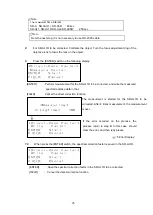
The SR-UL1R to be corrected changes to the function mode, and the [Direct-Conn Factor]-
[FACTOR] screen is displayed.
Moving to the Function Mode
☞
‘3.1.2 Entering/Return from the Function Mode’
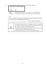
*Direct-Conn
Factor*
CHANGE:Setting


