10
4. Start Capacitor
The two wires of the start capacitor should be connected into the “4”terminal and “5” terminal.
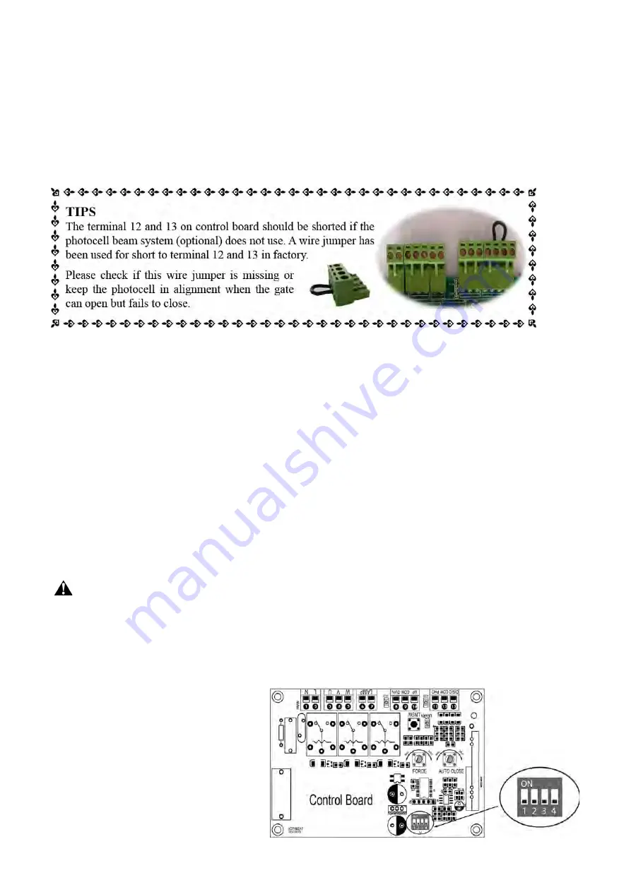
5. Photocell Beam System (PBS) (Included in some models, refers to the actual package)
Use a 2-core cable to connect the
“+ ~”
terminal of the photocell’s emitter to the “11” terminal, the
“- ~”
terminal to the “13” terminal. Also the
“+ ~”
and
“- ~”
terminals of the photocell’s receiver should be
connected to the “11” and “13” terminals in parallel.
Use another 2-core cable to connect the
“COM”
terminal of the receiver to the “13” terminal, the
“NC”
terminal to the “12” terminal.
6. Wired Keypad (12VDC) (Optional)
The
RED
wire of the wired keypad should be connected into the “11” terminal.
The
BLACK
wire of the wired keypad should be connected into the “13” terminal.
The
PURPLE
wire of the wired keypad should be connected into the “13” terminal.
The
BLUE
wire of the wired keypad should be connected into the “14” terminal.
7. Push Button (Optional)
The push button should be wired to the “13” and “14” terminals. The gate operator works alternately by
pushing the button (open-stop-close-stop-open).
8. External receiver (optional)
The
RED
wire of the external receiver should be connected into the “#11” terminal.
The
BLACK
wire of the external receiver should be connected into the “#13” terminal.
The
BROWN
wire of the external receiver should be connected into the “#14” terminal.
Setting of the Control Board
WARNING: Ensure the gate opener is Power Off when you make any adjustment of the gate
opener. Keep away from the gate during you set the gate opener system in case of the unexpected
gate moving. Carefully adjust the DIP switches to avoid the risk of machine damage and injury or
death. Always ask the help of professional technician /electrician if you have any question.
1. DIP Switches
The DIP switches are used to set the running time of the motor in pedestrian mode, enable/disable auto
close function of the gate operator and
fast change the open/close direction
which is determined by the position of the
gate operator installed.
DIP Switch #1–#2: Running time of the
motor in Midway Mode
DIP Switch #1: ON
– 2 Seconds
OFF
– 0
DIP Switch #2: ON
– 4 Seconds
OFF
– 0
NOTE: The midway mode function
Summary of Contents for CK700
Page 5: ...3 Parts List...


