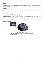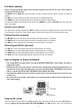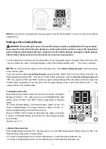
11
1.
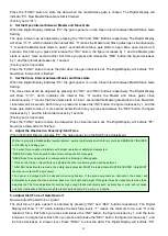
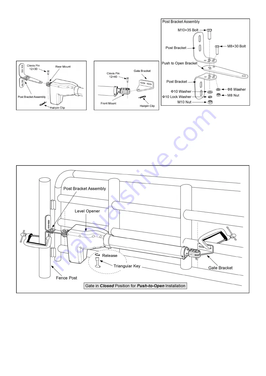
Insert the bolts through the holes of post bracket and
PSO part
(push to open bracket)
as shown. Place washers and nuts on the
bottom of the bolts and hand tighten.
2.
Attach the gate bracket and post bracket assy. to the opener by
inserting a clevis pin. Secure the clevis pins using the hairpin clips.
3.
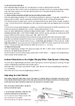
Insert the release key, and turn the key 90° clockwise. This releases the motor and allows the push-pull rod to
be manually extended and retracted. To restore normal operation, turn the key 90° counterclockwise.
4.
With the opener fully retracted and with the gate in the fully closed position (for Push-to-Open
installation)
, place the opener with the Post Bracket Assy. and Gate Bracket on the gate post and the gate.
While holding the gate opener in the level position, temporarily secure it with two C-clamps.
5.
Make sure that there is a minimum clearance of 2.5cm between the gate and the opener and that the opener
and the PSO part are not binding in both the gate-open and gate-closed positions. If there is not at least 2.5cm
of clearance or if the opener and the PSO part are binding, rotate the PSO part and/or move the Post Bracket
Assy. to obtain the minimum clearance and eliminate the binding.
Summary of Contents for KD902
Page 6: ...3 KD902 Parts List Accessories Parts Included in some models refers to the actual package...
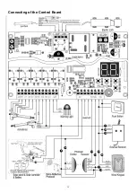
Page 18: ...15 Connecting of the Control Board...
Page 28: ...25 Quick Setting Guide...
Page 29: ...26...
Page 30: ...27...
Page 31: ...28...


