23
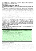
press the remote control to stop the opener. Use a screwdriver to loosen the screw of the limit B, slightly slide the limit
switch B
inwards.
If the arm closes halfway and fails to get to the desired closed position, slightly slide the limit switch B
outwards.
Please
repeat
the above steps, until the arm could arrive and automatically stop at the desired close position. Then
tighten the screw firmly.
Limit setting for master gate is finished now. The slave gate is totally the same.
2 For Push-to-Open Installation, adjust the limit switch B to determine the open position:
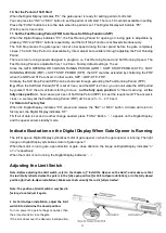
Turn on power to operate the gate opener, then the arm extends to open the gate.
If the arm opens over the desired open position, press the remote control to stop the opener. Use a screwdriver to
loosen the screw of the limit B, slightly slide the limit switch B
inwards.
If the arm opens halfway and fails to get to the desired open position, slightly slide the limit switch B
outwards.
Please
repeat
the above steps, until the arm could arrive and automatically stop at the desired open position. Then
tighten the screw firmly.
Limit setting for master gate is finished now. The slave gate is totally the same.
Maintenance
Warning:
Disconnect power before servicing.
1. Using a clean, dry cloth to wipe the gate opener shaft, and then apply a silicone spray to reduce its friction. In
cold climates where temperatures reach 1°C (30°F) or less, spray silicone on the actuator every 4~6 weeks to
prevent freeze up.
2. Regularly check gate hinges to make sure gate is swinging smoothly and freely. Grease hinges if needed.
3. Check your installation periodically, as hardware and posts will shift. Brackets may need to be adjusted or
hardware may need to be tightened.
4. Maintain the area around your gate. Keep the areas free of objects that can prevent the gate swinging freely.
NOTES:
1. Inspection and service should always be performed anytime a malfunction is observed or suspected.
2. It is suggested that while at the site voltage readings be taken at the operator. Using a Digital Voltmeter, verify
that the incoming voltage to the opener it is within ten percent of the opener
’s rating.
3. Refer to the instructions on how to check gate force and sensitivity adjustments.
Trouble Shooting
◆
Opener does not run. Digital Display indicator is not on.
1. Check if the power is on. Check the input voltage at the terminal. It should be local AC power. If the voltage
measures 0 suing the voltmeter, the power cable may be damaged.
2. Check if the output voltage of the transformer is 24Volts AC. If the voltage measures 0, the transformer may
be overheated or damaged. Turn power off and allow transformer to cool for several minutes then reset.
Replace the transformer if the symptom still exists.
3. Check the fuse in the control board. Replace the fuse if necessary.
Summary of Contents for KD902
Page 6: ...3 KD902 Parts List Accessories Parts Included in some models refers to the actual package...
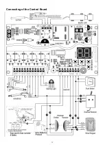
Page 18: ...15 Connecting of the Control Board...
Page 28: ...25 Quick Setting Guide...
Page 29: ...26...
Page 30: ...27...
Page 31: ...28...


