zmniejszając naciąg liny, za każdym razem odpowiednio o jeden skok
na kole zębatym.
Uwaga! Zawsze należy skontrolować stan liny, przed przystąpieniem do
pracy wyciągarką. Na dźwignie nie wolno wywierać siły w sposób
gwałtowny. Nacisk powinien zawsze być przykładany poprzez wywieranie
siły w sposób spokojny i równomierny.
II. PRZYKLADOWE OBCIAŻENIA DLA WYCIĄGRAKI O SILE UCIĄGU
2 TON.
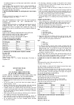
rys. C
Przykłady obciążenia dla wyciągarki o sile uciągu 2 ton
% nachylenia = wznios o 1 m / 100 m
NIE WOLNO PRZEKRACZAĆ NACHYLENIA 180% PRZY CIĄGNIĘCIU
ŁADUNKU. WYCIĄGARKA NIE JEST PRZEZNACZONA DO
PODNOSZENIA!
Uwaga! Podane powyżej liczby nie uwzględniają współczynnika tarcia. W
przypadku ładunków, które nie mają kółek lub innych rozwiązań
umożliwiających toczenie, wymagana będzie większa siła uciągu lub dla
podanych sił na rysunku masa ładunku musi być znacznie mniejsza od
2000 kg.
III. WYMIANA LINY
Specjalny otwór w bębnie wyciągarki pozwala na łatwą wymianę liny.
Należy w całości odwinąć linę zużytą z bębna wyciągarki.
Wyczepić starą linę z otworu w bębnie urządzenia.
Zaczepić koniec nowej liny w otworze bębna wyciągarki.
Nawinąć nową linę na bęben wyciągarki
IV. DANE TECHNICZNE WYCIĄGARKI
Nr katalogowy
97X080
97X082
Siła uciągu
2 t
3,5 t
Średnica liny
5 mm
5 mm
Przełożenie
15 : 1
15 : 1
Koło zębate
Podwójne
Podwójne
V. PRZYKŁADY ZASTOSOWANIA WYCIĄGARKI LINOWEJ
Wyciąganie łódki
Napinanie siatki
Usuwanie pni drzew
Przesuwanie, np. obrabiarki
GRUPA TOPEX Sp
z o.o. Spółka Komandytowa, Warszawa ul.
Pograniczna 2/4
EN
INSTRUCTIONS FOR USE
ROPE WINCH
CAT. NO. 97X080, TOWING FORCE 2 TONS
CAT. NO. 97X082, TOWING FORCE 3.5 TONS
CAUTION: BEFORE OPERATING THE ROPE WINCH, READ THIS
MANUAL CAREFULLY AND KEEP IT FOR FUTURE REFERENCE.
PRECAUTIONS FOR THE SAFE USE OF THE ROPE WINCH
•
Read and carefully follow the instructions in this manual when using the
rope winch.
•
For your own safety, the winch must never be overloaded above its
rated pulling force (... tons).
•
Make sure that the winch rope is always stretched, both when releasing
the pulling force and when starting to generate the pulling force.
•
If possible, always use a suitable hitching device attached to the object
on which the force generated by the winch will be exerted. Make sure
that the winch hooks are securely fastened so that they do not detach
during winch operation.
•
When working with the winch, make sure that there are no obstacles in
the workplace and that there are no bystanders nearby.
•
It is not allowed to
twist any object with the winch rope and do not
attach the hook to the rope. The rope must not rub against any corner.
•
Do not operate the winch if its rope is damaged (broken individual
wires), is bent or twisted.
•
Do not put any extensions (e.g. pipes) on
the winch lever to increase
the length of the lever. This can easily overload the lever and bend it or
even break it, damaging the winch.
•
It is not allowed to make any attempts to change the structure of the
winch.
•
Under no circumstances should you use the winch to lift any loads! The
winch is only used to exert a pulling force in a horizontal direction or in
an inclined to horizontal direction, provided that the extractable object is
in constant contact with the ground on which it is situated.
•
The winch operator must be instructed on how to use the winch and on
the potential dangers of not following the operating instructions of the
device.
I. USING THE ROPE WINCH
1.
When starting to pull out, first attach the rope hook to a certain hook
located on a stationary, stable object (wall, strong steel structure, etc.)
2.
Push the drive pawl spring in the direction of the arrow shown in fig1.
3.
Raise the lever and hold it securely in this position.
4.
Press the braking pawl in the direction shown by the arrow in fig. 1. At
the same time, pull the winch out to the desired distance.
fig.A
1.
Driving pawl
2.
Driving pawl spring
3.
Secure hook anchoring
4.
Braking pawl
5.
Engage the pawl and the toothed wheel (by pressing the drive pawl
spring in the opposite direction). Release the brake pawl. Each time the
lever is moved, the pulling rope will pull the load.
fig.A
1.
Gear
2.
Driving pawl
3.
Latch spring
6.
To release the tension, press the driving ratchet, gradually press the
lever until the brake ratchet disengages, as the driving ratchet presses
against the gear tooth. This will result in the loss of the tractive force
exerted on the load corresponding to one pitch on the gear wheel.
Repeat the movement of the lever, reducing the tension of the rope,
one step on the pinion at a time.
Warning! Always check the condition of the rope before starting work with
the winch. No force shall be applied violently on the levers. Pressure
should always be applied by applying force calmly and evenly.
II. EXAMPLES OF LOAD FOR A WINCH WITH A TOWING POWER OF
2 TONS.
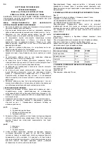
fig. C
Load examples for a winch with a pulling force of 2 tons
% of slope = 1 m / 100 m rise
DO NOT EXCEED A SLOPE OF 180% WHILE PULLING THE LOAD.
THE WINCH IS NOT INTENDED TO BE LIFTED!
Warning! The numbers given above do not include the friction coefficient.
For loads that do not have wheels or other rolling solutions, more tractive
force will be required, or for the forces shown in the figure, the weight of
the load must be significantly less than 2000 kg.
III. REPLACEMENT OF THE ROPE
A special hole in the
winch drum allows for easy rope replacement.
Fully unwind the used rope from the winch drum.
Unhook the old rope from the hole in the drum of the machine.
Hook the end of the new rope into the opening in the winch drum.
Wind the new rope onto the winch drum
IV. WINCH TECHNICAL DATA
Part number
97X080
97X082
Pulling force
2 t
3,5 t
Rope diameter
5 mm
5 mm
Gear ratio
15 : 1
15 : 1
Gear
Double
Double
V. EXAMPLES OF APPLICATION OF THE ROPE WINCH
Pulling out the boat
Tightening the mesh
Tree stump removal
Moving, e.g. machine tools


