multiSwitch – user manual
© TOPEX 2008 16
2.2.4 Electric circuit
The card contains a powerful processor controlling the whole PCI bus of the system.
The electric circuit includes multiple printed circuit cards and a hard disk for the operating system
(Gentoo Linux 2006), MultiSwitch application and storage of data.
It features on the front panel:
•
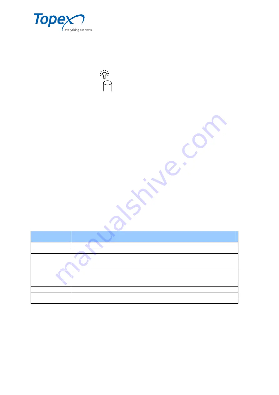
green LED (labeled with the
symbol) – shows the equipment power supply when it lights up;
•
orange LED (labeled with the
symbol) – shows the hard disk activity when it lights up.
On the back panel of the electric circuit we have:
•
2 x PS/2 connectors for mouse and keyboard connection;
•
4 x USB-A connectors (2 connectors in the left side, near the mouse / keyboard connectors, and
2 connectors in the right side, under the Ethernet connector);
•
DB 27 female connector for the printer connection;
•
DB 9 male connector;
•
DB 15 female connector for the PC monitor connection;
•
Ethernet connector for the local network;
•
3 connectors – 2 (blue and yellow) for connecting the head phones and speakers and the pink
one for connecting a microphone.
2.2.5 PC Server Specifications
TOPEX multiSwitch application can be installed on several PC servers which must achieve a
minimum configuration described earlier. In case of the PC Servers delivered by TOPEX along with
the multiSwitch application installed the usual server is a HP Proliant DL140G3 type.
The HP PC Server specifications are detailed below:
Model
HP Proliant DL140 G3 5140
Processor
Dual-Core Intel® Xeon® processor 5140 (2.33 GHz, 65 W, 1333 MHz FSB)
Cache Memory
4MB (1 x 4MB) Level 2 Cache or 8 MB (2 x 4MB) Level 2 Cache
RAM Memory
1 GB FBD PC2-5300 DDR2 Fully Buffered DIMMs (667 MHz) – 2 x 512 kit
Network
Controller
Two embedded NC320i PCIe Gigabit Server Adapters
Storage
Controller
HP 8 Internal Port SAS HBA with RAID
Internal storage
36 GB 15 K SAS Hot plug hard drive 3.5”
Optical Drive
HP DL320 RoHS DVD RW
Form Factor
Rack 1U
Installation Kit
HP 5140 DL140 G3


