background image

Application Note: Security, Alarm System 

www.topkodas.lt


17  | 

E N


Wiegand Keypad & RFID Card Reader. Wiring & Programming. 


Sera2> System Options> Digital I/O Settings 
Sera2> Users/ Access Control  


O

U

T1

C

O

M

BU

S

O

U

T4

I/O

1

IN

4

IN

3

IN

2

D

3

O

U

T2

+3

.3

V

O

U

T3

D

1

D

2

VD

+

C

O

M

IN

1

I/O

2

1

2

3

4

5

6

7

8

9

esc

0

ENT

-

+

-

+

Bell

Buzzer

co

m

12

V

D

1

D

0

Led

Gtalarm 2


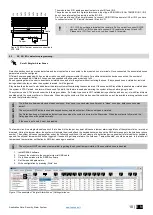
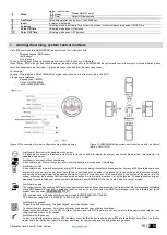
Figure 25Wiegand keypad connection 


Wiegand bus specifications:


26bit Wiegand (Default);  


8bit key press code 

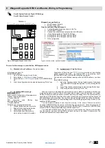
Steps to configure Wiegand keypad: 

1. 

Connect Wiegand keypad as shown in the Fig  

2. 

Install SERA2 software. 


3. 

Connect the module to the computer via mini USB cable. 

4. 

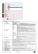
„Go to System options“> Digital I/O Settings 

5. 

Set Digital I/O D2 to Wiegand  interface Data0 

6. 

Set Digital I/O D3 to Wiegand  interface Data1 

7. 

Write configuration 


Figure 26 How to find "System Options > Digital I/O Settings window 

 
There is 3 different ways, to enter iButton, RFID keycard codes: 
 

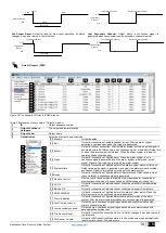
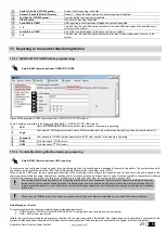
A)  Manually in Sera2 software. 

(The picture below) 


In that case, you have to: 
Install SERA2 software 

1. 

Go to “Users& Remote Control” table. 

2. 

Enter iButton 

or RFID Keycard 

codes for users.  

3. 

Select  iButton 

or  RFID  Keycard

  action  OUT/ARM/DISARM, 

etc. 

4. 

Write the con

figuration into the module by pressing “Write” icon 


B)  Automatically in Sera2 software. 


Association  of iButton keys  or

  RFID  Keycards 

is  carried  out  by  activating 

special  programming  mode  - 

by  sending  SMS  or  by  pressing  „Learn 

iButtons/RFID mode“ in the SERA2 configuration program.  
If you need to enter iButtons learning mode by SERA2 software, you have 
to: 
Install SERA2 software. 

1. 

Go to 

the “System options> General system options” and press 

“Start iButton/RFID programming mode” to start entering iButton 
keys. 

2. 

Press “Stop iButton programming” to stop entering iButton keys. 

3. 

Write configuration by pressing “Write” icon.


C)  by sending SMS message:


INST123456

˽063˽S 

INST = Install. Configuration of the parameters.  
123456= Installer‘s password 
˽= Space character  
063= 

command 

code 

(iButton 

keys 

learning/deleting mode) 
˽= Space character  
S=iButton keys entering/deletion mode. 

0- 

Disable iButton keys learning mode,  

1- 

Enable iButton keys learning mode, 

2- 

 iButton keys deleting mode, 

3- 

Delete these keys from memory, 
which will be touched to the reader. 

When  you  receive  a message into  your mobile  phone in relation  to  activation  of  iButton  key 

programming  mode,  touch  the  key  to  the  reader  and  its  unique  code  will  recorded  into  system 
memory. Buzzer will notify you about successful recording by beeping twice. The system allows to 
associate up to 800 iButton keys. Each time when touching the key, the system records its code till 
all desirable keys will be recorded. If during 2 minutes not a single iButton key will not be learned, 
the system will automatically exit keys learning mode. After finishing programming of the keys, you 
might send SMS message. 

You  can  disable  recording  of  new  keys  into  memory.  In  the  event  of  failure  to  send  this 

message,  ARM/DISARM  of  the  system  via  iButton  key  will  not  operate.  Control  functions  for  all 
newly associated keys will be assigned according to MASTER key. For example: If MASTER key 
will control Out1, all newly associated keys will also control Out1.  

You can delete all iButton keys from the memory. If you have the key, that you want to delete 

from the memory,  you  have to send  SMS,  and touch the key  to  the  reader.  2 minutes  later, the 
module will deactivate the keys deletion mode. 


Summary of Contents for GTalarm2

Page 1: ...GTalarm2 Application Note Security Alarm System Monitoring alarm control This manual includes steps to install set up and use your system...

Page 2: ...PGM outputs 24V 1000mA Open Drain Digital expansion module BUS In field firmware upgrade via USB SERA Cloud Remote Service Events log buffer 2048 events Program remote controls using the master or ins...

Page 3: ...or to the server 1 3 First steps to prepare GTalarm2 module and Sera2 software Preparation procedure of the module GTalarm2 Connect the GSM antenna to the antenna connector Insert the SIM card in the...

Page 4: ...r supply Battery Wiring It is possible to supply the security system from stabilized power supply source 10 15 V and not less than 1 5A It is necessary to calculate max current of power supply The cur...

Page 5: ...sed or used as security system s zones with selectable type NC NO EOL EOL TAMPER 2 programmable analog inputs I O1 I O2 0 10V 0 20mA that can be used or used as security system s zone with selectable...

Page 6: ...Monitoring control via mobile phone web browser GTalarm2 Figure 5 Monitoring control via mobile phone web browser Figure 7 Monitoring via web mobile app Zone status 4 2 Monitoring via SERA2 software...

Page 7: ...Application Note Security Alarm System www topkodas lt 7 E N Figure 8 Monitoring via free Sera2 software Zone status...

Page 8: ...2012 configurable as encrypted and non encrypted Shock sensor Reporting to the central monitoring station GTalarm2 Figure 9 Reporting to the central monitoring station 4 4 Local alarm For protecting...

Page 9: ...able analog inputs I O1 I O2 0 10V 0 20mA for analog sensors control or using as security system s zone with selectable type NC NO EOL EOL TAMPER 5 1 NC NO EOL detectors wiring It is recommended to us...

Page 10: ...owing conditions If a Delay type zone is NOT violated during exit delay and a zone s with Stay attribute enabled exists the system will arm in Stay mode When arming the system in Stay mode under this...

Page 11: ...xcept the module will auto bypass the zone if Armed in the Stay mode 6 Wiring Type Type EOL End of line resistor Input type with resistor NC Normal Close The alarm will be send when the circuit betwee...

Page 12: ...ectors Figure 20 2 wire smoke detector wiring diagram o If I O1 I O2 set as 2 wire don t need connect 5 1k resistor to VD o I O1 I O2 do not have internal pull up resistors So if you want to connect N...

Page 13: ...inuous signals generated and if the alarm system is disturbed pulse signal Signal is terminated by turning off the alarm system OFF ON Flash Open Command ARM Close Alarm Open Remote Control Output des...

Page 14: ...nuous signals generated and if the alarm system is disturbed pulse signal Signal is terminated by turning off the alarm system 25 System State Output for connection of light indicator of the alarm sys...

Page 15: ...arm the system and turn OFF the alarm by dialing the system s phone number from any of 800 available user phone numbers The system ignores any incoming calls from a non listed phone number The phone c...

Page 16: ...smission Delay to enter a valid 4or 6 digits Security Code before the Central Monitoring Center CMS is notified If a valid Security Code is not entered within the 30 seconds then a message is sent to...

Page 17: ...and press Start iButton RFID programming mode to start entering iButton keys 2 Press Stop iButton programming to stop entering iButton keys 3 Write configuration by pressing Write icon C by sending SM...

Page 18: ...elow 9 2 Enter iButton keys by sending SMS message A Send SMS message to the module GTalarm2 INST123456 063 S INST Install Configuration of the parameters 123456 Installer s password Space character 0...

Page 19: ...y In order to delete the code it is necessary to enter 000000000000 7 OUT The selected input will be switched if a user will call from this number Preferred input may be assigned to each user s number...

Page 20: ...t is necessary to enter 000000000000 6 Keyb Code Key button code might be entered manually In order to delete the code it is necessary to enter 000000000000 7 OUT The selected input will be switched i...

Page 21: ...er tamper recognition 18 Tamper Disable The module will not generate an alarm or trouble 19 Trouble when disarmed alarm as per zone when armed When disarmed Generates Trouble Only The module transmits...

Page 22: ...d busy signal b The system will continue dialing the next listed user phone numbers in the priority order The system will dial again as many times as programmed and the same order as phone numbers lis...

Page 23: ...tem can be configured to report events to the monitoring station by transmitting data messages to the monitoring station The system connects to the central monitoring station when the CMS Central Moni...

Page 24: ...station to receive the connection requests TCP mode or the datagrams UDP mode transmitted by ALERT 2 Backup 1 Backup 1 central monitoring station settings 7 Transport Protocol TCP or UDP The used lin...

Page 25: ...Code Format A 4 digit or 6 digit user access code format can be selected 6 I O1 Settings 2 Wire Smoke detector Fire current loop or 0 10V Analog Input Zone or Sensor or Output or 0 20mA 4 20mA Curren...

Page 26: ...ton stops the monitoring of the module 3 IMEI IMEI number of GSM modem available in the module 4 SIM ICCID ICCID Integrated Circuit Card Identifier A SIM card contains its unique serial number ICCID I...

Page 27: ...rm shutdown for the zone is activated Allowable number of the same alarm events is reached and the same events will not be reported 6 Bypassed If checked and the color is red the zone is bypassed 7 Fo...

Page 28: ...seller with the questions about the configuration you have to Press Read icon first to read the configuration from the module the press File Save us and save the configuration Save the Events Log file...

Page 29: ...l be taken to match sensor range to room size A sensor whose range extends well beyond the boundaries of the room is acoustically hot and vulnerable to false alarms For protecting glass on more than o...

Page 30: ...icable laws codes or standards for a specific type of occupancy approved single and multiple station smoke alarms shall be installed as follows 1 In all sleeping rooms and guest rooms 2 Outside of eac...

Page 31: ...ted on the other side of closed or partly open doors If warning devices sound on a different level of the residence from the bedrooms then they are less likely to waken or alert people inside the bedr...

Reviews: