GTalarm3 User manual V-2022-05-24
17 |
E N
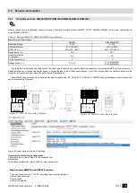
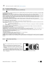
Using cat 5 cable is best and will make it easier to maintain a working 1-wire network when you expand and add more sensors. The data and
ground should use one twisted pair, for example blue/blue-white. A single wire from another pair is used for the 3.3 volt supply.
Don't double up wires on the assumption that this lowers resistance and is a 'good thing', it actually alters the impedance of the network and makes
it less reliable. All unused wires in the cat 5 cable should be left unconnected (don't connect them to ground).When running a 1-Wire bus, Dallas recommend
that you use an unshielded Cat5 cable for the bus. Do not use shielded cable as the capacitance increase will upset the network.
If you intend to have a large 1-Wire network, it is important that you design the network correctly, otherwise you will have problems with
timing/reflection issues and loss of data. You must connect each sensor to a single continuous cable which loops from sensor to sensor in turn (daisy
chain). This will reduce potential miss-reads due to reflections in the cable. Each sensor should have a maximum of 50mm (2") of cable connected off this
main network. Even when using this method, connecting more than 10-15 sensors will still cause problems due to loading of the data bus. To minimize
this effect, place a 100-
120Ω resistor in series in the data line of each sensor before connecting to the network. The total length of the bus from 10 to 100m.
Depending of cable quality sensors number on bus, and environment noise. There is possibility to connect up to 32 devices.
Begin the installation by mounting additional devices in the cabinet using the stand-offs provided, then mount the cabinet in a dry, protected area
with access to unstitched AC power. Install hardware in the sequence indicated in the following pages. Do NOT apply power until installation is complete.
All circuits are classified UL power limited except for the battery leads. Mi
nimum ¼” (6.4mm) separation must be maintained at all points
between power limited and non-power limited wiring and connections.
3.3.3.2
Temperature sensors Dallas 1-wire DS18b20 Configuration
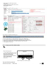
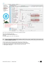
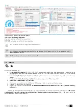
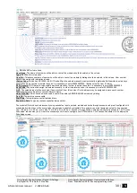
Step by step to start DS18b20 sensors:
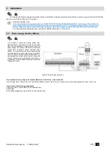
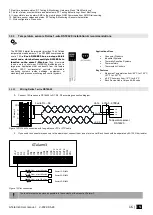
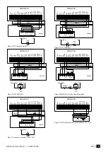
1. Connect 1-Wire sensors DS18b20 to D1 or D2, D3 according connection diagram.
If you need to connect more sensors to the same input, connect them
as a star or serial.
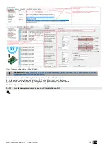
2. Set digital input definition D1, D2, D3 to Dallas 1-Wire Bus option
3. Write configuration
4. Power the module.
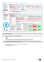
5. After module starts. Within few seconds, it will automatically scans and registers all connected 1-Wire sensors on the bus.
6. Read configuration
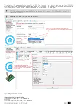
7. Double click on the selected line
8. Select the registered sensor.
9. Set the required parameters.
10
. Press “Write”
If you want to edit existing configuration
,
You have to read it (press “Read” in the command line)
Edit settings
Write edited configuration (press “Write” in the command line)


