GTalarm3 User manual V-2022-05-24
10 |
E N
3
Installation
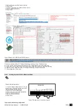
This Installation & Programming manual provides the basic installation, wiring and programming information required to program the module GTalarm3
and connect all third party devices to the module.
Humidity sensors , AM2302/DHT22/AM2305/AM2306/AM2320/AM2321
Analog inputs 0-10V, 0-20mA, 4-
Burglar Alarm sensor zones wiring EOL NO NC
[4-Wire] Smoke detector Wiring
Output PGM wiring. Bell, Relay, Led Wiring
Wiegand Keypad & RFID Card Reader Wiring
iButton keys
.
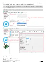
You can find detailed explanation about every field in SERA2 software here:
3.1
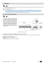
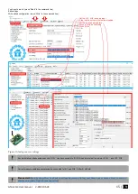
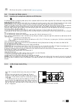
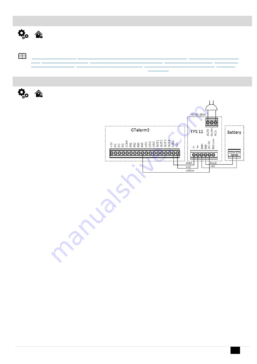
Power supply, Battery Wiring
It is possible to supply the security system from
stabilized power supply source 10-15 V and not less
than 1,5A. It is necessary to calculate max current of
power supply. The current of the alarm system is the
current used by sensors, relays, siren and other
devices. It is most convenient to use power supply
source applied for power supply of security systems
with the option to connect backup lead battery. It is
recommended to mount remote control relays into
sockets. Sockets may be easily fixed in metal box. It
is necessary to select relays according to preferred
voltage and current.
Figure 5 Power supply connection
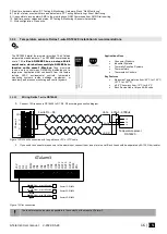
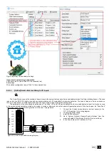
The example how to configure the module GTalarm3 for AC failure, restore function
Go to “Burglar Alarm Zones” window in the SERA2 software. Double click on the 4
th
row and enter the required parameters. Press “save” icon.
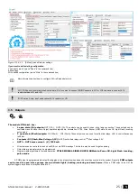
If you want to edit existing configuration
,
You have to read it (press “Read” in the command line)
Edit settings
Write edited configuration (press “Write” in the command line)


