GTalarm3 User manual V-2022-05-24
14 |
E N
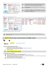
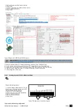
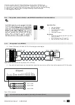
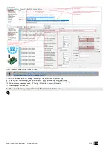
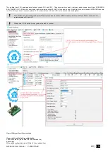
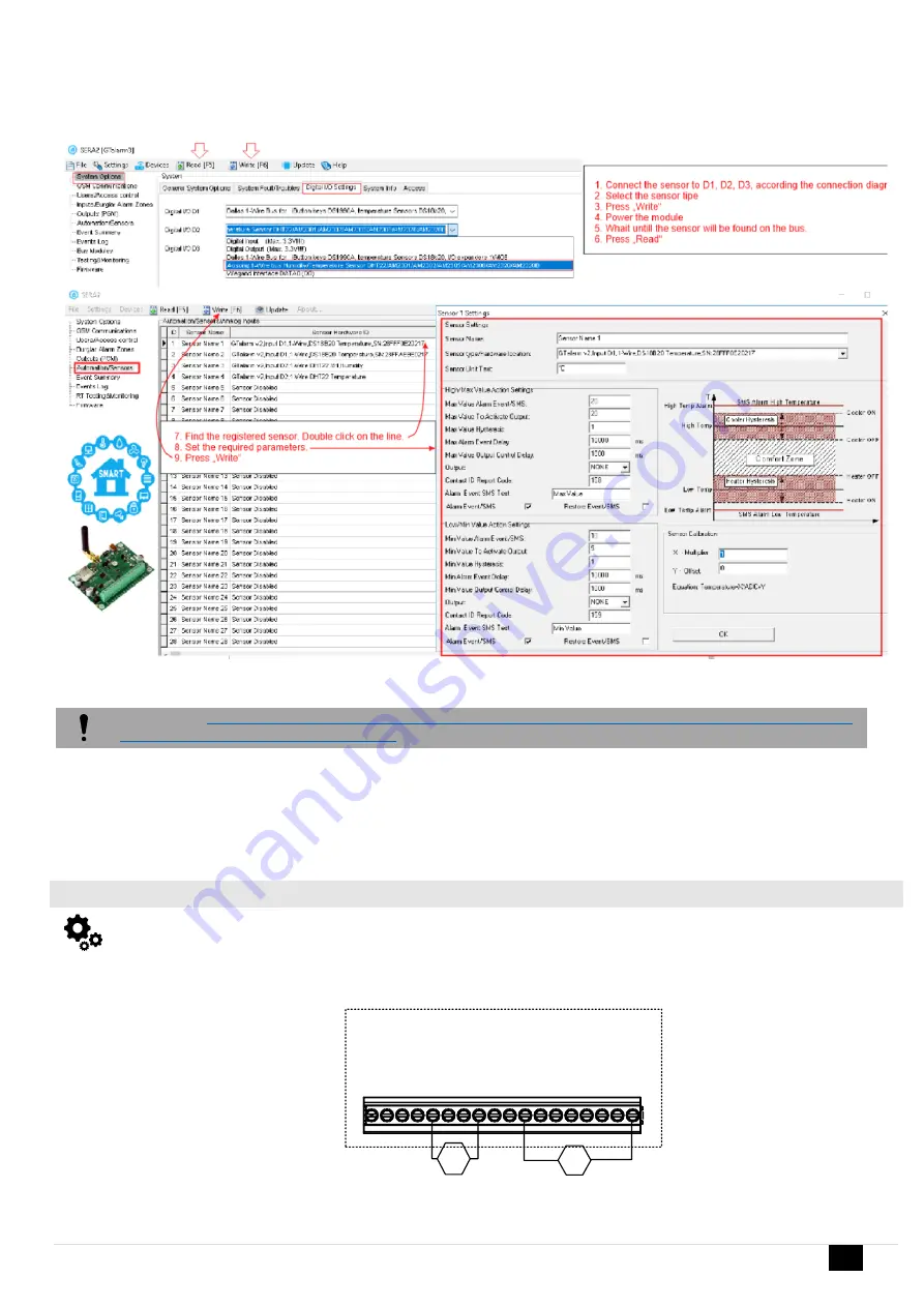
5. Wait until the sensor will be found on the bus.
6. Press „Read“
7. Find the registered sensor. Double click on the line.
8. Set the required parameters.
9. Press „Write“
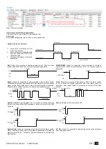
Figure 9Steps to start AM2320 and AM2302 sensors:
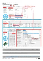
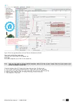
Step by step: How to check real time hardware status, real time sensor values. How to receive
alarms and where find alarm events list?
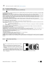
7. Real time hardware status: RT
Testing & Monitoring> Hardware. Press “Start Monitoring”
8. The list of alarm events with time and date stamp: RT Testing & Monitoring> Event Monitoring
9. It is possible to receive alarm SMS to the mobile phone: GSM Communication> SMS/ Dial reporting
10. Real time sensor values and states: RT Testing & Monitoring> Sensors/ Automation.
11. Write configuration. Press write.
3.3.2
Analog inputs 0-10V, 0-20mA, 4-20mA
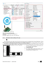
Steps to start analog sensors:
1. Connect analog voltage sensors to In1, In2,
In3 and connect analog current sensors to I/O1,
I/O2 according connection diagram..
2. Set the I/O1, I/O2 to analog input
3. If the input is not used, it must be disabled.
4. Set the required parameters.
5. Sensors could be calibrated.
6.
Press „Write“
V
A
4-20mA
0-10V
I/
O
3
C
O
M
O
U
T4
O
U
T3
I/
O
1
IN
4
IN
3
IN
2
D
3
O
U
T1
+5
V
O
U
T2
D
1
D
2
VD
+
C
O
M
IN
1
I/
O
2
GTalarm3
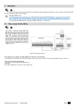
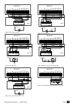
Figure 10Analog sensors connection diagram
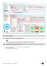
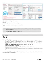
If you want to edit existing configuration
,


