background image

GTM1 User manual    V-2020-08-12 


48  | 

E N


INST000000

˽020˽N 

Invert output state 

020= command code (outputs inversion) 
N = output number from 1 to 10.


INST000000

˽021˽N#ST 

Output activation or deactivation 

021= command code (Output activation or deactivation) 
N = output number 1-10 
ST = output mode 0 

– OFF, 1- ON 


INST000000

˽022˽N#TIME# 

Output activation for the time interval  

022= command code (Output activation for the time interval) 
N = output number 1-10 
TIME = 0-999999 Time interval in seconds for the output activation. 


INST000000

˽030˽ST  

Change securi

ty system‘s mode (ARM/DISARM/STAY/SLEEP)  

030= command code (Change security system‘s mode) 
ST = 0-DISARM, 1-ARM, 2-STAY, 3-SLEEP 


INST000000

˽031˽ZN#BYP 

Zone bypassing by sms command 

031= command code (Zone bypassing) 
ZN = zone number from 1 to 32 
BYP= 1 

– zone bypass 0- zone active. 


INST000000

˽063˽S 

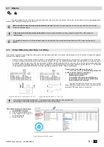
iButton keys learning/deleting mode 

063= command code (iButton keys learning/deleting mode) 
S=iButton keys entering/deletion mode. 
0-Disable iButton/RFID keys learning mode  
1-Enable iButton/RFID keys learning mode 
2- iButton/RFID keys deleting mode.  To delete these keys from memory, which will be touched to 
the reader


INST000000

˽070˽N#VALUE # 

Programming of  max sensors value upon reaching, the SMS message with „High Alarm“ 
text will be sent 

070= command c

ode (max sensors value upon reaching which, the SMS message with „High 

Alarm“ text will be sent) 
N = sensor number 
VALUE= Format 0000.00 High Alarm Value 


INST000000

˽071˽N#VALUE # 

Programming of  minimal sensors value upon reaching the SMS message with „Low Alarm“ 
text will be sent 

071= command code (min sensors value upon reaching which, the SMS message with „Low Alarm“ 
text will be sent) 
N = sensor number 
VALUE = Format 0000.00 Low Alarm Value


INST000000

˽072˽N#VALUE# 

Programming of sensor max value upon reaching the selected output will be activated. 

For 

example cooling equipment


072= command code (sensor max value upon reaching the selected output will be activated.)  
N = sensor number 
VALUE= Format 0000.00 sensor max value upon reaching, the selected output will be activated. 


INST000000

˽073˽N#VALUE# 

Programming of sensor min value upon reaching the selected output will be activated.

 For 

example heating equipment 
073= command code (sensor min value upon reaching the selected output will be activated.)  
N = sensor number 
VALUE= Format 0000.00 Sensor min value upon reaching which, the output will be activated.


INST000000 090 NEW_INST_PSW  

Change installer‘s password

 (Installers password should be changed before exploitation of the 

module) 
090= command code (Change of installer‘s password) 
NEW_INST_PSW 

= New Installer‘s password. 


INST000000 091 NEW_USER_PSW  

Change user‘s password


(User‘s password should be changed before exploitation of the module) 

091= command code (Change user‘s password) 
NEW_USER_PSW = New user‘s password.


INST000000

˽092 

Remote reset of the module via SMS messages  

092= command code (Remote reset of the module via SMS messages ) 


INST000000 093 yyyy/MM/dd#HH:mm# 

Time of the module setting via SMS message 

093= command code (Time of the module setting via SMS message) 
Time format of the module: 
yyyy/MM/dd#HH:mm# 
yyyy -year  
MM-month 1-12  
dd - day of the month 1-31  
HH-hours 0-23  
mm- minutes 0-59 


INST000000

˽094˽TEL#SMS 

SMS from the module forwarding to the other phone number 


SMS from the module forwarding to the other phone number 
094= command code (SMS from the module resending to the other phone number) 
TEL = phone number to which will be forwarded sms textSMS = sms text that will be send to 
the referred number. 

Summary of Contents for GTM1

Page 1: ...GTM1 Installation Programming Manual Security monitoring control and automation system This manual includes steps to install set up and use your system...

Page 2: ...2G Quad band 850 900 1800 1900 MHz or 4G LTE modem INPUTS IO1and IO2 programmable selectable input or output IO1 0 30V IO2 0 30V IO3 D0 programmable selectable IO3 D0 0 30V analog input zone or senso...

Page 3: ...to read event log from internal memory of the module 27 4 2 10 How to set SMS alarms 27 4 2 11 Burglar Alarm sensor zones wiring EOL NO NC 27 4 2 12 Fire alarm and Smoke sensors 29 4 2 12 1 Guidelines...

Page 4: ...s Humidity Sensor AM2302 DHT22 AM2305 AM2306 AM2320 AM2321 Voltage 5V Current limit 100mA AUX 10 30V 1A Output state indication LED FN Automatic periodical test Test sending in a form of SMS message P...

Page 5: ...ich is used for system arming and disarming Installer a person provided with INST installer s password Master User Code Allows to carry out system arming disarming as well as minor system configuratio...

Page 6: ...A F5 key iButton probe with LED indicator GSM antenna with cable GSM antenna 1 pcs Humidity sensor AM2305 Water Proof DS18b20 Temperature Probe with 1m cable Temperature sensor DS18B20 Humidity sensor...

Page 7: ...ly The memory of the module contains unsent reports to the user or to the server Off All reports has been send FN blue built in LED ON OFF Selected output or input ON Selected output or input OFF Tabl...

Page 8: ...Options General system options It is automatically ignored if pin request in SIM card is disabled Installer Password 000000 SERA2 System Options General system options This password allows you to ent...

Page 9: ...lt index php Settings Figure 5 GSM Communication Sera Cloud Service App Key and Settings App Key Figure 6 https cloud topkodas lt index php Settings App Key 1 7 2 Installer and User passwords The pass...

Page 10: ...aster Code for access control via keypad Defaul Master code 1234 or 123456 1 Select 6 or 4 digits user access code format Sera2 System Options General System Options User Access Code Format 2 Enter 6...

Page 11: ...r containing installation of the software SERA2 Click the file SERA2 setup exe If installation directory of the software is OK press Next If you would like to install the software in the other directo...

Page 12: ...current used by sensors relays siren and other devices It is most convenient to use power supply source applied for power supply of security systems with the option to connect backup lead battery It i...

Page 13: ...s lt website HELP SUPPORT Downloads Go to SERA2 Inputs Burglar Alarm Zones Double click on the 4th row Figure 18 SERA2 Inputs Burglar Alarm Zones Enter the required parameters Press Write icon in the...

Page 14: ...08 12 14 E N Figure 21 SERA2 Inputs Burglar Alarm Zones Double click on the selected line How to set SMS alarm funkction Go to SERA2 GSM Communication SMS DIAL reporting Figure 22 SERA2 GSM Communica...

Page 15: ...wer supply TPS12 installation manual https topkodas lt Downloads TPS12_UM_EN pdf Power supply TPS12 https topkodas lt Downloads GTalarm2_TPS12_AN_EN pdf AC equipment cannot be connected directly to th...

Page 16: ...s PREPARE the module GTM1 Insert SIM card Screw GSM antenna Connect analog current sensor as in the diagram Connect the power supply Connect the module to the computer via mini USB Install SERA2 softw...

Page 17: ...the command line Figure 27 SERA2 Automation Sensors Double click on the line Figure 28 SERA2 Automation Sensors Double click on the selected line Change default settings under your requirements Press...

Page 18: ...2321 Operating Range 0 100 0 100 Absolute accuracy RH 25 C 3 10 90 5 10 90 3 10 90 5 10 90 Repeatability 0 3 0 1 Long term stability per year 0 5 0 5 1 e Response sec 5 5 Voltage supply V 3 3 5 5 3 1...

Page 19: ...configuration press Write in the command line Connect the module to the computer via mini USB cable Connect the power supply Start free configuration program Sera2 You will find it in https www topko...

Page 20: ...ERA2 Automation Sensors window The sensor will appear in the list automatically Double click on the selected sensor s line Figure 33 SERA2 Automation Sensors Set other parameters of the sensor MIN MAX...

Page 21: ...analog voltage sensors to IO3 IN1 according connection diagram If sensor connected to IO3 go to SERA2 System Options General System options Set IO3 to 0 30V Analog Input Zone or Sensor Press Write in...

Page 22: ...Each DS18B20 has a unique 64 bit serial code which allows multiple DS18B20s to function on the same 1 Wire bus Thus it is simple to use one to control many DS18B20s distributed over a large area Appl...

Page 23: ...isting configuration You have to read it press Read in the command line Edit settings Write edited configuration press Write in the command line Connect the module to the computer via mini USB cable C...

Page 24: ...etwork and makes it less reliable All unused wires in the cat 5 cable should be left unconnected don t connect them to ground When running a 1 Wire bus Dallas recommend that you use an unshielded Cat5...

Page 25: ...Fahrenheit If you want to edit existing configuration You have to read it press Read in the command line Edit settings Write edited configuration press Write in the command line 1 Go to SERA2 Automat...

Page 26: ...igger point Example The wanted minimum temperature is 19 C So sensor1 Min 19 and Hysteresis 0 5 4 2 8 How to test the system hardware status real time sensor values event list Real time hardware statu...

Page 27: ...ttings Write edited configuration press Write in the command line Alarm SMS to the mobile phone Go to SERA2 GSM Communication SMS DIAL reporting Enter your phone number Mark alarm events Press Write i...

Page 28: ...EOL NC With EOL NO With EOL NC With EOL Wire Fault Recognition NC Contacts No EOL NC With EOL NO With EOL NC With EOL Wire Fault Recognition PROGRAMMING If you want to edit existing configuration You...

Page 29: ...areas that should be protected include the basement bedrooms especially where smokers sleep dining rooms furnace and utility rooms and any hallways not protected by the required units On smooth ceilin...

Page 30: ...d fireplaces In exhaust streams from gas engines vents flues or chimneys In close proximity to an automobile exhaust pipe this will damage the detector Progate Begin the installation by mounting addit...

Page 31: ...the zone should be defined as a Fire Zone I O1 and I O2 can be defined as a 2 wire smoke detector input if a line short occurs or the smoke detector activates whether the system is armed or disarmed t...

Page 32: ...r Alarm Zones Set Zone Definition to fire Set the required parameters Press Write in the command line Figure 58 SERA2 Inputs Burglar Alarm Zones 4 3 Alarms to the mobile phone to the Central Monitorin...

Page 33: ...system Go to SERA2 RT Testing Monitoring Hardware Press Start Monitoring button Go to SERA2 RT Testing Monitoring Security Alarm Panel Access You will see the real time status Figure 59 SERA2 GSM Com...

Page 34: ...nt Monitoring You will see real time events list Figure 65 SERA2 RT Testing Monitoring Event Monitoring 4 6 Read events log Go to SERA2 Events Log Press Read Event Log button Figure 64 SERA2 RT Testin...

Page 35: ...double insulation cable Auxiliary BUZZER is recommended to be installed inside the premises not far from the entrance Buzzer operates together with the main siren also when the system starts calculati...

Page 36: ...ration press Write in the command line Quick start outputs 1 Install SERA2 software For more information look at SERA2 Uploading Downloading Software 2 Connect the module to the computer via mini USB...

Page 37: ...alarm system OFF ON Flash Open Command ARM Close Alarm Open Remote Control Output designed for connection of electrical devices which will be controlled by SMS message or phone call a control by SMS...

Page 38: ...nnel Lost Secondary Channel Restore Primary Channel 4 7 6 Access control output with logging If you want to edit existing configuration You have to read it press Read in the command line Edit settings...

Page 39: ...way but it will not generate 421 and 422 events Event log e g 1853 Event 1234 1 401 01 001 Time 2017 08 20 14 42 36 Note Open by User User 001 Name Master 1852 Event 1234 1 422 00 001 Time 2017 08 20...

Page 40: ...ts it and carries out arming disarming procedure afterwards If there is more than one listed user dialing to the system at the same time the system will accept the incoming call from the user who was...

Page 41: ...rd keyfob To arm disarm the system with RFID keycard touch 1 of 800 RFID keycard to the Wiegand keypad When the RFID keycard is touched to the reader for arming disarming the system will proceed armin...

Page 42: ...tem will notify about successfully recording of the key into memory by shortly beeping twice via buzzer The system will automatically assigns control function ARM DISARM The first key is the main key...

Page 43: ...ns General System Options Go to SERA2 System Options General System Options Press Start iButton RFID Phone programming mode Figure 88 SERA2 System Options General System Options Go to SERA2 Users Acce...

Page 44: ...haracter 063 command code iButton keys learning deleting mode Space character S iButton keys entering deletion mode 0 Disable iButton keys learning mode 1 Enable iButton keys learning mode 2 iButton k...

Page 45: ...t be necessary again to set the same parameters If you want to save that is already recorded by the module firstly you must read configuration of the module Press Read 4 icon In order to save configur...

Page 46: ...m configuration control and request for information By default installer code is 000000 which is highly recommended to change User code 6 digit password used for system control and request for informa...

Page 47: ...elete user s phone number whose ID number is N 006 command code Delete user s phone number according user s ID number N user s ID number from 001 to 800 INST000000 007 P PER HH mm Automatic periodical...

Page 48: ...be sent N sensor number VALUE Format 0000 00 Low Alarm Value INST000000 072 N VALUE Programming of sensor max value upon reaching the selected output will be activated For example cooling equipment 0...

Page 49: ...on input output states and system state ARM DISARM STAY 9 The table of users commands The phone number must be in the Sera2 Users Access control list if USER123456 commands will be used If the phone...

Page 50: ...tc 2 the values of active sensors request 3 Request about active zone states 4 Request about output states 5 System state request The module will send information on input output states and system sta...

Page 51: ...ations or foreign objects Damage caused by peripherals unless such peripherals were supplied by UAB Topkodas Defects caused by failure to provide a suitable installation environment for the products D...

Page 52: ...aping gas and improper storage of flammable materials overloaded electrical circuits and children playing with matches or arson Even if the smoke detector operates as intended there may be circumstanc...

Reviews: