BTA User Guide
Topling Prnjavor
Page 32
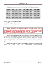
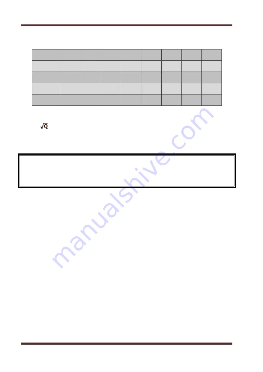
Table 8.
Dimensions of min. intake and outake holes of fresh air in the boiler room.
Q (kW)
350
450
550
750
1000
1200
1500
2000
A
0
(cm
2
)
3741
4243
4690
5477
6325
6928
7746
8944
a
o
xb
0
(cm)
61x61
65x65
69x69
74x74
80x80
84x84
88x88
95x95
A
1
(cm
2
)
1247
1414
1563
1827
2108
2309
2582
2981
a
1
xb
1
(cm)
35x35
38x38
40x40
43x43
46x46
48x48
51x51
55x55
A
0
(cm
2
)
– surface of openings for air supply
A
0
= 200
, Q (kW) - power of boiler
A
1
(cm
2
) - surface of openings for air outlet
A
1
= 1/3
.
A
0
Boiler and burner must be distant and protected from parts of
flammable building materials and built-in furniture so that temperatures
of mentioned boiler heating capacity over 80 º C cannot occur.
Otherwise, you must maintain a distance of at least 80 cm.
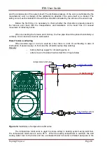
Mouth for the air intake and outake must always be open, in its full cross section.
Air intake must be directly from outside. Air intake must be located 50 cm the most above
the bottom edge of the tank. The air intake mouth is preferably placed under the ceiling
on the outer wall of the boiler. If the boiler does not have outer walls, the ventilation
needs to be regukated by channel distribution. The air outake mounth must not have a
grid.
Minimum recommended distance from the wall for the assembly and maintenance
should
be
taken
from
the
manufacturer's
recommendations.
Summary of Contents for BTA1000
Page 70: ...BTA User Guide Topling Prnjavor Page 70...
Page 71: ...BTA User Guide Topling Prnjavor Page 71...
Page 72: ...BTA User Guide Topling Prnjavor Page 72...
Page 73: ...BTA User Guide Topling Prnjavor Page 73...
Page 74: ...BTA User Guide Topling Prnjavor Page 74...
Page 75: ...BTA User Guide Topling Prnjavor Page 75...
Page 76: ...BTA User Guide Topling Prnjavor Page 76...
Page 77: ...BTA User Guide Topling Prnjavor Page 77...
Page 78: ...BTA User Guide Topling Prnjavor Page 78...
Page 79: ...BTA User Guide Topling Prnjavor Page 79...

