background image

- 14 - 


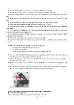
Fig.25D-Loose and replace the pump.


Warning: make sure that you have pulled the Plug from the main socket when you do the   

following maintenance. 
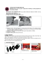
1.  Clean the pump 

To clean the pump, remove the intake cover, and then take out of the filter foam 

and impeller cover. Use a small brush or stream of water to remove any debris on the foam and the 
impeller. (Fig.25A) 

Note: Please clean the pump immediately after you stop use

.

 Otherwise the dry debris could 

stick the filter foam and the impeller, which will cause you to replace the filter foam or the 

pump. 

2.  Replace the filter foam

 To replace the filter foam, remove the intake cover, then take out of the 

filter foam and put into a new one.
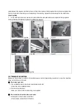
   

3.  Replace the pump 

After replacing new filter foam, if the pump still does not work, you have to 

replace problem pump with a new one, only use the pump recommended by the manufacturer of 
the machine. The changing procedures are as follows:


3.1 Loosen the bolt of the pump connecting box located inside the main frame and remove the cover 

(Fig.25B). 

3.2 Loosen the bolt of the pump cable lock and take the pump plug out of connecting box (Fig.25C, 

25D). 

3.3 Take out the pump and replace a new one, install the new pump by reversing above procedures   

Note: Only an authorized person should perform other repairs! 


B. ALIGNMENT MAINTENANCE  

This saw motor or bridge does not need to be squared up or aligned, since the bridge does not allow 
the saw motor to move. When it appears that the saw is out of alignment, it is the rip fence that needs to 
be squared up.   

Tools needed: 

24” Framing Square, Phillips Screw Driver and 1/4

 Nut Driver or Pliers 

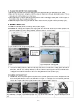
The following steps should be used to align the rip fence for the Bridge Saw: 

1.  Pull the power unit towards you and lock in place with the transport lever. 
2.  Once the power unit is secured, place the Framing square firmly against the blade on the 
left side of the cutting surface. The square must be flush with the blade. 

(See Fig.26A)

3.  Slide the square into the rip fence, making sure the square stays firmly against the blade. Look for 
a gap between the square and the rip fence. If there is a gap, adjustments will be necessary. 

(See 

Fig.26B)


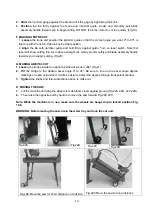
4.  To adjust the gap, first remove the Angle cutting guide. This will expose two screws in the 
aluminum track. Loosen both screws in the extruded aluminum bar. 

(See Fig.26C&D) 

5.  From underneath the saw, directly below the rip fence, there are two 1/4

 bolts located under the 

left rip fence and 2 bolts under the right rip fence. Loosen both bolts for the rip fence that you are 
adjusting. 

(See Fig.26E&F) 

6.  Once the screws are loose, easily slide the rip fence above, allowing you to close the 

Summary of Contents for FTD-202A

Page 1: ...erate the machine properly familiarize yourself with the controls and make sure you know how to stop it quickly in an emergency Save this user s manual and the other documents supplied with this machi...

Page 2: ...S 9 V INSTALLATION AND OPERATING 9 A STARTING AND STOPPING THE SAW 9 B ASSEMBLY 9 C FILLING THE WATER TRAY AND DRAINING 11 D MAKING A PUNCH CUT 11 E MAKING A STRAIGHT CUT 12 F MAKING A MITRE CUT 12 G...

Page 3: ...9dB A LpA 99 1dB A Uncertainty KpA 1 5 m s2 Uncertainty KpA 1 5 m s2 The sound power level of the machine No load LwA 84 4dB A LwA 85 3dB A Uncertainty KwA 1 5 m s2 Uncertainty KwA 1 5 m s2 Under loa...

Page 4: ...the bias 45 90 degree The diamond blade is cooled by water pump Use only the continuous rim diamond blade recommended by the manufacturer Warning Never attempt to cut wood metal and other similar mate...

Page 5: ...in the work touch the tool or the extension cord and keep them away from the work area 5 Store idle tools When not in use tools should be stored in a dry locked up place out of reach of children 6 Do...

Page 6: ...re doing use common sense and do not operate the tool when you are tired 20 Check damaged parts Before further use of tool it should be carefully checked to determine that it will operate properly and...

Page 7: ...firmly against the rip fence Ensure that the work piece that will be cut off has sufficient room to move sideways Failure to do so may result in the off cut binding against the blade Never cut more t...

Page 8: ...followed Observe the code of practice drawn up by the trade association Operation of the cutter in confined spaces is permissible only if a suitable suction extraction system is used Caution Switch of...

Page 9: ...cable is required please note that with a cable length of up to 20 m cable with a cross section of 1 5 mm must be used To start the saw press the green button marked I To stop the saw press the red bu...

Page 10: ...nance and transportation 6 For wider tile than the main table designed the extension table should be pulled out to support the tile Fig 13 7 Install the wheel accessory on to the designed leg Fig 14A...

Page 11: ...upward and press the handle for punch cutting DO NOT force the motor to cut too quickly Fig 15 make sure the pin goes into pinhole Fig 16 loose butterfly knob for punch cut Fig 17 Fig 18 Adjust the c...

Page 12: ...wards you to begin cutting Fig 20 G MAKING A BEVEL CUT 1 Loosen the knobs located on each rail stand of stoner cutter Fig 21 2 Tilt the bridge to the desired bevel angle 0 to 45 Be sure to line up the...

Page 13: ...t material to be cut is against the direction of rotation 3 Replace the flange back and adjust the blade to get the best balance of Blade 4 Fix the lock nut tightly 5 Close the blade guard and secure...

Page 14: ...ocedures Note Only an authorized person should perform other repairs B ALIGNMENT MAINTENANCE This saw motor or bridge does not need to be squared up or aligned since the bridge does not allow the saw...

Page 15: ...ghten in place for additional support Fig 26A Fig 26B Fig 26C Fig 26D Fig 26E Fig 26F Fig 26G VII TROUBLE SHOOTING Below we have listed a number of possible causes and corresponding solutions in case...

Page 16: ...y your supplier VIII ACCESSORIES 1 Rip miter cutting guide 2 Hexagonal blade wrench 3 Motor shaft holding wrench 4 Handle IX SERVICE AND ADDRESS TOPMAQ 32 Hammersmith Drive Wigram Christchurch 8042 TE...

Reviews: