background image

CONTROL ELEMENTS

7- 75 Hz Low-Cut Switch (MX.10/USB V2, MX.12/USB V2 only)

8- +4/-10 Switch (

only)

MX.10/USB V2, MX.12/USB V2

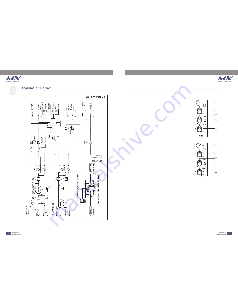
9- AUX Send (except MX.5 V2)

These switches are used to select the input sensitivity of the
line inputs on the stereo channels. +4 dBu is suitable for
professional audio devices and -10dBv is suitable for general
devices. If not sure to use which setting, try +4 dBu first,
then change it to -10dBv if the volume is too small to be
satisfied.

By pressing this button you will activate a 75Hz low frequency
filter that cuts the bass frequency below 75Hz. You can use this
switch to reduce the hum noise caused by the mains power
supply, or the stage rumble while using a microphone.

This control is used to feed the mono input of parallel effects
devices or the input of a stage monitor amplifier via the AUX
SEND output jack. All the channel controls (except PAN or BAL)
will affect the AUX signal. The signal is tapped off after the LEVEL
control. The output from an external processor can come back
via STEREO AUX RETURN inputs(on the MX.6/USB V2) or stereo
channel (MX.10

MX.12

), and be added to the main mix.

/USB V2,

/USB V2

6- LOW EQ

This is the bass control. It is used to boost male voice, kick-drum
or bass guitar. Your system will sound much bigger than what
it is. The gain range goes from -15 dB to +15 dB and the center
frequency is 80 Hz.

8

9

10

11

12

10- PAN/BAL

Abbreviation of PANORAMA control for mono channels, for the stereo channels, always says,
BALANCE control. You can adjust the stereo image of the signal via this control. For mono
MIC/LINE channels, keep PAN control in centre position and your signal will be positioned in
the middle of stage that is to say the mono signal appears equally in both sides. Turn this
control fully counterclockwise and the signal will be present only on the left speaker and
vice-versa. For stereo channels, by rotating the BAL control, you can attenuate the signal of
left or right. It means if turn the control to left, the right channel will be attenuated; if turned
to right, the left channel will be attenuated.

11- PEAK LED

When this LED blinks, it warns you that you are reaching signal saturation and possible distortion.
From this LED you can adjust the correct level, not too strong to cause distortion and not too weak
to be lost in noise.

7

9

10

11

12

7

5

Summary of Contents for MX.10 USB V2

Page 1: ...MX SERIES MIXER MX SERIES MIXER ...

Page 2: ...2 The mains plug or an appliance coupler is used as the disconnect device the disconnect device shall remain readily operable ...

Page 3: ...OF CONTENTS 1 INTRODUCTION 4 2 FEATURES 4 4 CONTROL ELEMENTS 6 6 WIRE CONNECTIONS 12 3 USEFUL DATA 4 5 INSTALLATION TIPS 11 7 BLOCK DIAGRAM 13 8 TECHNICAL SPECIFICATION 17 9 GUARANTEE 19 3 4 HOOKUP DIAGRAM 5 ...

Page 4: ... 10 USB V2 MX 12 USB V2 MX 6USB V2 MX 10USB V2 MX 12USB V2 1 mono inputs with gold plated XLR and Balanced TRS jack inputs with Balanced TRS jack 2 stereo 2 band EQ on all mono channels 2 Track IN OUT Balanced XLR TRS jack output MX 5 V2 2 mono inputs 4 for MX 12 USB V2 with gold plated XLR and Balanced TRS jack 4 2 for MX 6 USB V2 stereo inputs with Balanced TRS jack GAIN control and 48V phantom ...

Page 5: ...AT Recorder Drum Machine Active Speakers Small Club Gig Computer Set up Direct Box Direct Box Guitar Digital Audio Interface Digital Audio Interface Digital Audio Workstation Digital Audio Workstation Headphones MIC 1 MIC 1 Drum Machine Drum Machine Active Studio Monitors Active Studio Monitors 5 ...

Page 6: ... 1 4 TRS balanced and TS unbalanced LINE IN plug you can connect with line level instruments such as synthesizers keyboards drum machines or effect devices Never try to connect a line level signal to the XLR MIC input when the phantom power is engaged doing this you may seriously damage your equipment NOTE They are organized in stereo pair and provided with 1 4 TRS sockets It is used to connect th...

Page 7: ...V2 or stereo channel MX 10 MX 12 and be added to the main mix USB V2 USB V2 6 LOW EQ This is the bass control It is used to boost male voice kick drum or bass guitar Your system will sound much bigger than what it is The gain range goes from 15 dB to 15 dB and the center frequency is 80 Hz 8 9 10 11 12 10 PAN BAL Abbreviation of PANORAMA control for mono channels for the stereo channels always say...

Page 8: ... will need a Y splitter RCA adapter 14 TAPE OUTPUTS 16 TAPE TO CTRL RM PHONES Switch TAPE TO PHONES on MX 5 V2 Switch is used to select the signal source for the CONTROL ROOM outputs PHONES and METERS Release this switch they all receive the main mix signal tapped after the MAIN MIX control Engage this switch they all receive the CD TAPE Input signal Turn down the CTRL ROOM PHONES control just PHO...

Page 9: ...is may cause damage NOTE 22 METERS This stereo LED meter will indicate the level of the overall output signal 23 MAIN MIX This control sets the level of main mix signals sent to the Main Outputs Tape Outputs CONTROL PHONES and LED Display On the MX 5 V2 and MX 6 USB V2 this is a rotary control on MX 10 and MX 12 this is a fader When connecting a speaker to the speaker output jacks please pay more ...

Page 10: ...puts The level is controlled by the CTRL ROOM PHONES knob You can listen to the Main Mix the CD TAPE or the AUX SEND MX 10 USB V2 MX 12 USB V2 depending upon the position of the TAPE TO CTRL RM PHONES switch and FX TO CTRL ROOM switch Rear Panel 28 POWER IN This connection is where you connect the supplied external AC power supply to provide AC power to the mixer Connect the external power supply ...

Page 11: ...omeone Care should be taken as to not damage the cabinet or its components Please comply with all pertinent Regulations 3 Use quality cables Using quality cables will ensure the best possible sound 4 For best results match the speakers to a good amplifier that matches the wattage and impedance of your speakers Proper amplification power results in good quality audio and longer component life Check...

Page 12: ... Tip Sleeve Tip Sleeve Tip Sleeve Cent e r Cent e r Centre Screen Screen Screen 1 2 3 Tip Ring Sleeve 1 2 3 1 2 3 Tip Ring Sleeve 1 2 3 Tip Sleeve 1 2 3 TIP SLEEVE TIP SLEEVE TIP RING SLEEVE TIP RING SLEEVE 1 2 3 2 1 3 2 1 3 TIP RING SLEEVE TIP SLEEVE 1 2 3 1 2 3 SLEEVE TIP SLEEVE RING TIP For these applications the unit provides 1 4 TRS and XLR connectors to easily interface with most professiona...

Page 13: ...BLOCK DIAGRAM MX 5 V2 13 8 ...

Page 14: ...BLOCK DIAGRAM TAPE OUT R TAPE OUT L TAPE IN R TAPE IN L Built in USB V2 Audio interface This section only for MX 6 USB V2 TAPE OUT L TAPE IN R TAPE OUT R TAPE IN L MX 6 USB V2 14 8 ...

Page 15: ...BLOCK DIAGRAM MX 10 USB V2 TAPE OUT R TAPE OUT L TAPE IN R TAPE IN L Built in USB V2 Audio interface This section only for MX 10 USB V2 TAPE OUT R TAPE OUT L TAPE IN R TAPE IN L 15 8 ...

Page 16: ...BLOCK DIAGRAM TAPE OUT R TAPE OUT L TAPE IN R TAPE IN L Built in USB V2 Audio interface This section only for MX 12 USB V2 MX 12 USB V2 TAPE OUT R TAPE OUT L TAPE IN R TAPE IN L 16 8 ...

Page 17: ...er 0 dBu 1 kHz 0dBu 0dBu 0dBu 0dBu Maximum Output Level Main Aux Control Room output all knob fader 0 dBu 1 kHz 22 Hz 22 kHz Filter THD 1 22dBu 22dBu 22dBu 22dBu Maximum Voltage Gain EQ and PAN BAL knob 0 dB Other all knob or fader max DFX mute 1 kHz Rs 600 Mono Channel MIC INPUT MAIN OUT 1 4 TRS Unbalanced Mono Channel MIC INPUT CTRL RM PHONES 1 4 TRS Stereo Mono Channel MIC INPUT AUX SEND OUT 1 ...

Page 18: ...Meters Clip 19 6 0 20 0 LED 0 dBu Microphone Input Line Input Impedance CD Tape Input Main Outputs Ctrl Room Aux Sends Tape Output Phones Outputs 2 6k Ohms 10k Ohms 20k Ohms 120 Ohms 120 Ohms 1K Ohms Mic Pin2 Pin3 And Pin1 XLR 3 31 type balanced 1 GND 2 HOT 3 COLD Phantom power 2 6k Ohms 10k Ohms 20k Ohms 120 Ohms 120 Ohms 1K Ohms 2 6k Ohms 10k Ohms 20k Ohms 120 Ohms 120 Ohms 1K Ohms 2 6k Ohms 10k...

Page 19: ...19 10 ...

Page 20: ......

Reviews: