CONTROL ELEMENTS
MX .12FX
MX .12FX
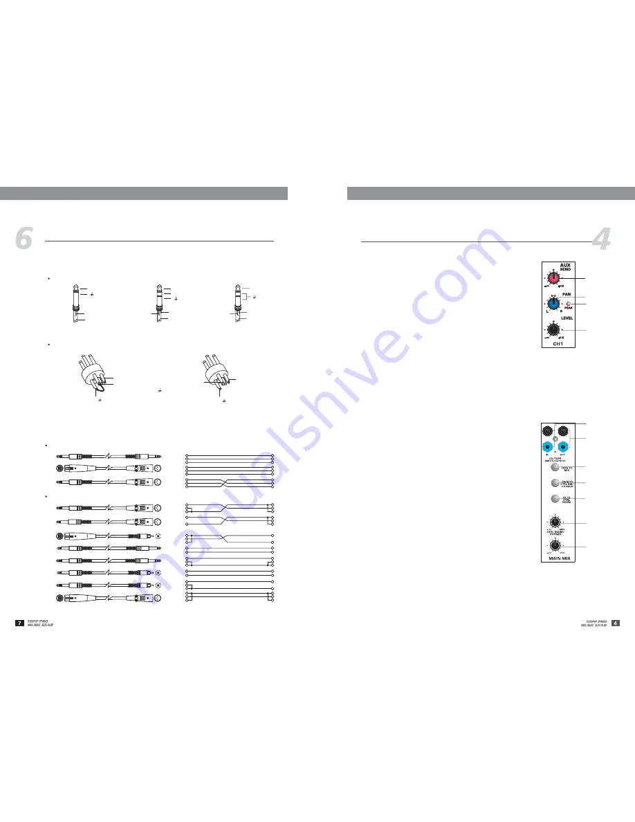
12- LEVEL
This control will adjust the overall level of this channel. If you set the LEVEL control in max, it's usually a sign
that your GAIN is set too low. If set the LEVEL control in min, your GAIN may be too high.
10- PAN/BAL
Abbreviation of PANORAMA control for mono channels, for stereo channels,
always says, BALANCE control. You can adjust the stereo image of the signal
via this control. For mono MIC/LINE channels, keep PAN control in centre
position and your signal will be positioned in the middle of stage that is to
say the mono signal appears equally in both sides. Turn this control fully
counterclockwise and the signal will be present only on the left speaker and
vice-versa. For stereo channels, by rotating the BAL control, you can attenuate
the signal of left or right. It means if turn the control to left, the right channel
will be attenuated; if turned to right, the left channel will be attenuated.
11- PEAK LED
When this LED blinks, it warns you that you are reaching signal saturation and
possible distortion. From this LED you can adjust the correct level, not too strong
to cause distortion and not too weak to be lost in noise.
9
10
11
12
13- CD/TAPE INPUTS
These RCA jacks will assign the main out signal to a tape recorder or DAT. The
TAPE OUT level is affected by MAIN MIX control.
Use the Tape Input if you wish to listen to your mixer from a Taper Recorder or DAT. When the TAPE TO MIX
switch is pushed in, the signal coming from Taper Recorder will assign to main mix; when the CD/TAPE switch
which on the front panel is engaged in the signal can also be assigned to the CONTROL ROOM/PHONES
outputs. If you connect a mono device, you will need a "Y-splitter" RCA adapter.
14- TAPE OUTPUTS
18- CTRL ROOM/PHONES Control
16- TAPE TO CTRL RM/PHONES Switch
Switch is used to select the signal source for the CONTROL ROOM outputs,
PHONES, and METERS. Release this switch, they all receive the main mix
signal tapped after the MAIN MIX control. Engage this switch, they all receive
the CD/TAPE Input signal. Turn down the CTRL ROOM/PHONES control before
engaging.
15- TAPE TO MIX Switch
Connect a CD or Tape Deck to the CD/TAPE inputs, and push down this switch
to add the CD/TAPE signal to the main mix. The volume level is controlled by
MAIN MIX control.
17- FX TO CTRL ROOM Switch
Engage this switch to monitor the aux send signal in the Control Room/
Phones outputs.
This control is used to adjust the signal level going to the CONTROL ROOM/
PHONES outputs. And it won't affect the Main Mix output.
19- MAIN MIX
This control sets the level of main mix signals sent to the Main Outputs, Tape Outputs, CONTROL
PHONES,
and LED Display.
When connecting a speaker to the speaker output jacks, please pay more attention to the level setting for
avoiding damaging the speaker. Generally speaking, the faders will be positioned between 0 dB and the +5 dB.
Note:
ROOM,
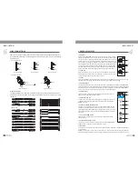
WIRE CONNECTIONS
Either the 1/4" TRS phone jack or XLR connector can be wired in balanced and unbalanced modes,
which will be determined by the actual application status, please wire your system as the following
wiring examples:
XLR Type Unbalanced
Pin3 (-)
Pin2 (+)
Pin1 ( )
(Linked to Pin1 manually,
)
XLR Type alanced
B
Pin1 ( )
Pin2 (+)
Pin3 (-)
Tip
Ring
Sleeve
Tip
Ring
Sleeve
Tip
Ring
Sleeve
1
2
3
1
2
3
1
2
3
TIP RING SLEEVE
SLEEVE RING TIP
TIP RING SLEEVE
2
1
3
1
2
3
1
2
3
Tip
Ring
Sleeve
Tip
Ring
Sleeve
Tip
Sleeve
Tip
Sleeve
Tip
Sleeve
Cent e
r
Cent e
r
Centre
Screen
Screen
Screen
1
2
3
Tip
Ring
Sleeve
1
2
3
1
2
3
Tip
Ring
Sleeve
1
2
3
Tip
Sleeve
1
2
3
TIP SLEEVE
TIP SLEEVE
TIP RING SLEEVE
TIP RING SLEEVE
1
2
3
2
1
3
2
1
3
TIP RING SLEEVE
TIP SLEEVE
1
2
3
1
2
3
SLEEVE TIP
SLEEVE RING TIP
For these applications the unit provides 1/4" TRS and XLR connectors to easily interface with most
professional audio devices. Follow the configuration examples below for your particular connection.
Unbalanced
In-line Connection
Balanced
TRS Type Balanced
Tip
Ring
Sleeve
+
-
TRS Type Unbalanced
Tip
Ring
Sleeve
+
TS Type Unbalanced
Sleeve
Tip
+
For 1/4" Phone jack
For XLR Connector
19
13
14
15
16
17
18


