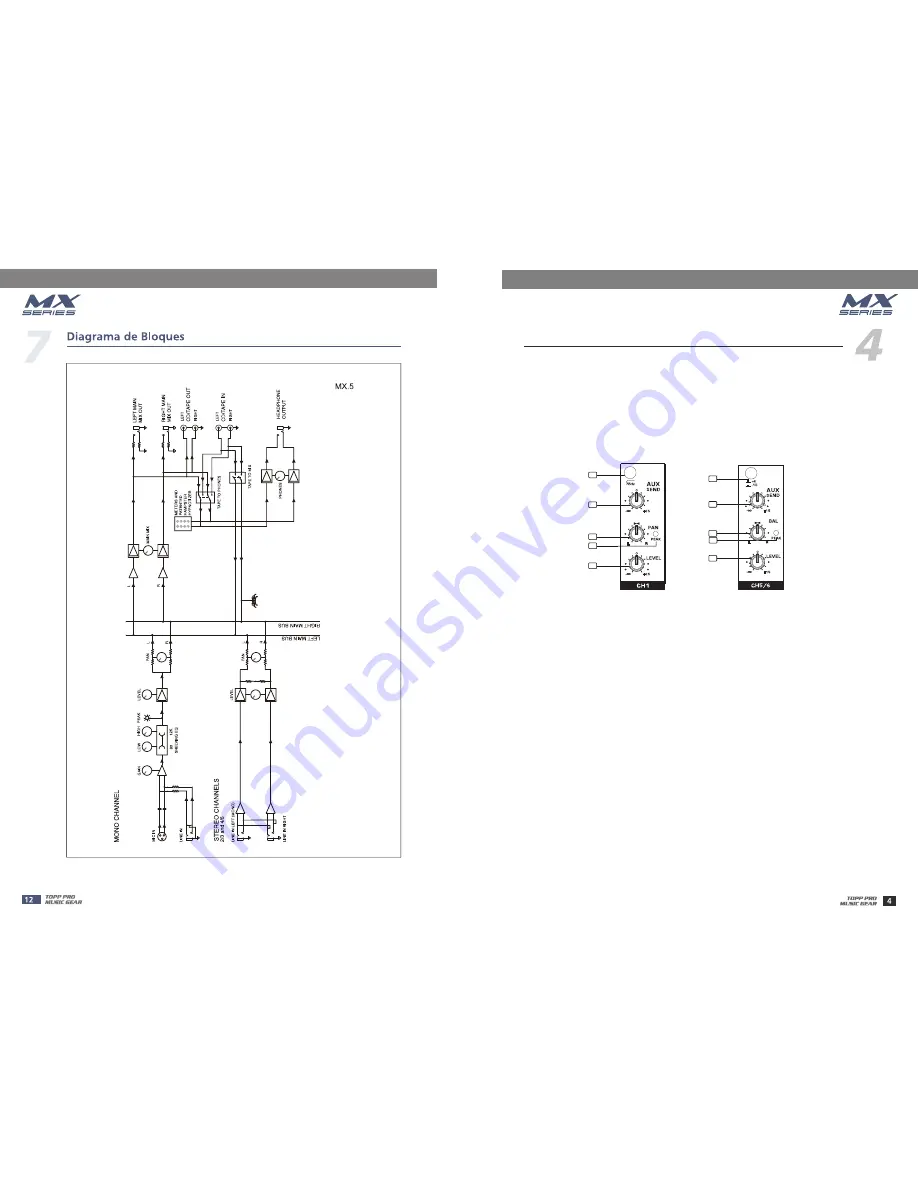
CONTROL ELEMENTS
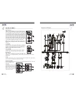
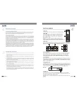
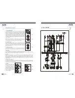
7- 75 Hz Low-Cut Switch (MX.10 USB/MX.12 USB only)
8- +4/-10 Switch (MX.10 USB/MX.12 USBonly)
9- AUX Send (except MX.5)
These switches are used to select the input sensitivity of the line inputs on the stereo
channels. +4 dBu is suitable for professional audio devices and -10 dBv is suitable
for general devices. If not sure to use which setting, try +4 dBu first, then change it
to -10 dBv if the volume is too small to be satisfied.
By pressing this button you will activate a 75Hz low frequency filter that cuts the bass
frequency below 75Hz. You can use this switch to reduce the hum noise caused by the
mains power supply, or the stage rumble while using a microphone.
This control is used to feed the mono input of parallel effects devices or the input of a stage
monitor amplifier via the AUX SEND output jack. All the channel controls (except PAN or BAL)
will affect the AUX signal. The signal is tapped off after the LEVEL control. The output from an
external processor can come back via the STEREO AUX RETURN inputs (on the MX.6USB)
or stereo channel (MX.10USB/MX.12USB), and be added to the main mix.
7
8
9
9
10
10
11
11
12
12
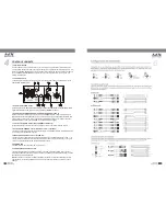
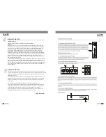
12- LEVEL
This control will adjust the overall level of this channel. If you set the LEVEL control in max,
it's usually a sign that your GAIN is set too low. If set the LEVEL control in min, your GAIN
may be too high.
10- PAN/BAL
Abbreviation of PANORAMA control for mono channels, for the stereo channels, always
says, BALANCE control. You can adjust the stereo image of the signal via this control.
For mono MIC/LINE channels, keep PAN control in centre position and your signal will be
positioned in the middle of stage that is to say the mono signal appears equally in both
sides. Turn this control fully counterclockwise and the signal will be present only on the
left speaker and vice-versa. For stereo channels, by rotating the BAL control, you can
attenuate the signal of left or right. It means if turn the control to left, the right channel will
be attenuated; if turned to right, the left channel will be attenuated.
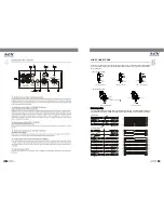
11- PEAK LED
When this LED blinks, it warns you that you are reaching signal saturation and possible distortion.
From this LED you can adjust the correct level, not too strong to cause distortion and not too
weak to be lost in noise.


