background image

 CONTROL ELEMENTS

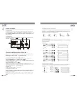
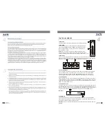
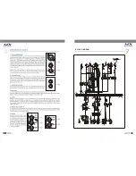
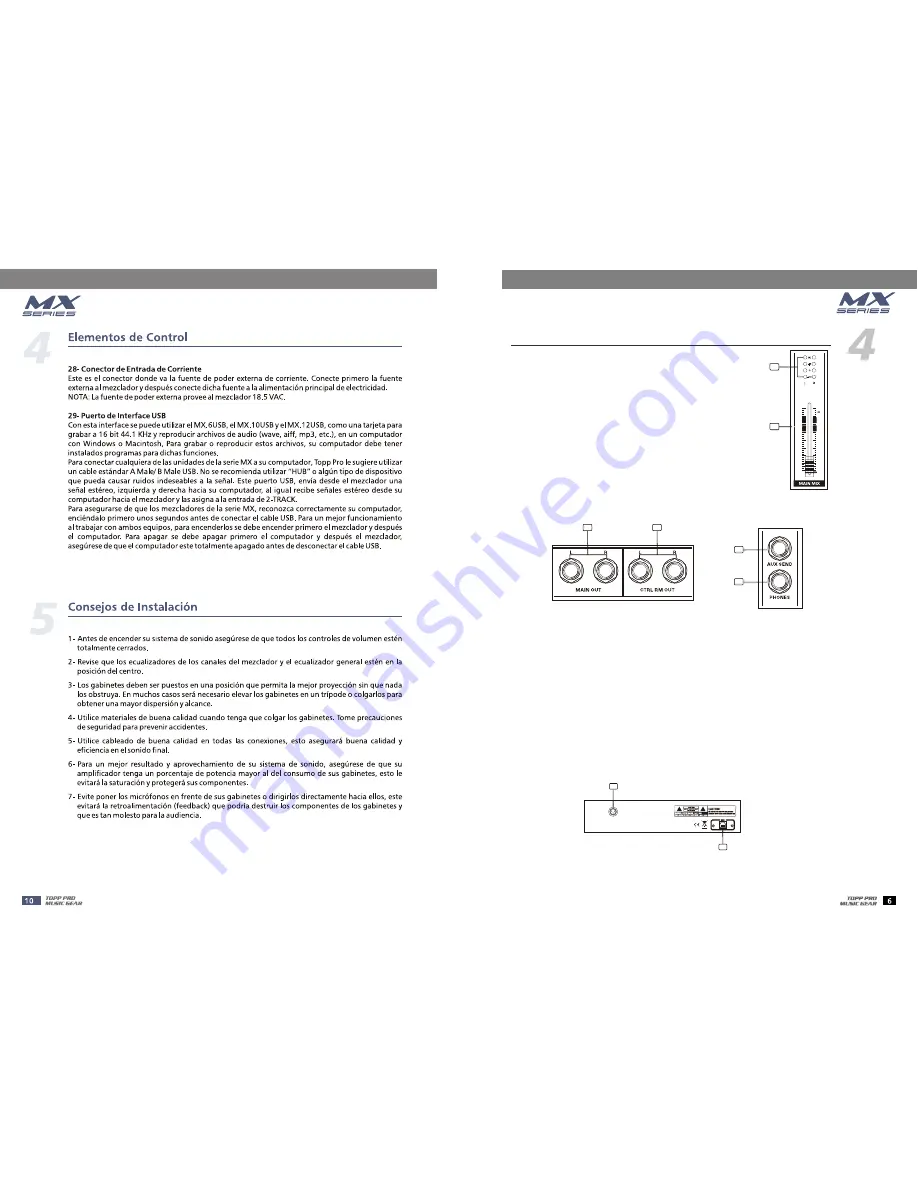
22- METERS 

This stereo LED meter will indicate the level of the overall output signal.

23- MAIN MIX 

This control sets the level of main mix signals sent to the Main Outputs, 
Tape Outputs, CONTROL 

PHONES, and LED  Display. On the 

MX.5 and MX.6 USB, this is a rotary control; on 

MX.10 USB and 

MX.12 USB, this is a fader. 


Note:

When connecting a speaker to the speaker output jacks, please


pay more attention to the level setting for avoiding damaging the speaker.


Generally speaking, the faders will be positioned between 0 dB and the +5 dB.

ROOM, 

the  

-60

-50

-40

-30

-20

-10

-5

0

5

10

22

23

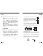
25- CTRL ROOM OUT 

26- AUX SEND OUT 

27- PHONES OUTPUT 

These 1/4" TRS are used to assign the control room signal to the studio monitor speakers. 
They can also be used to provide another main mix output, or to monitor the CD/TAPE 
Inputs (when engage the TAPE TO CTRL RM/PHONES switch), or to monitor the aux 
send signal (MX.10 USB/MX.12 USB only with FX TO CTRL ROOM switch is engaged)

These 1/4" TRS are used to send out the signal from the AUX bus to external device such 
as effects equipment. Each channel has an AUX SEND control knob that adjusts how much 
of that channel's signal appear at each of the output. This output is affected by the channel 
LEVEL, but not MAIN MIX control.    


This jack is used to send out the mix signal to a pair of headphones, and the signal is the same as 
the CTRL RM OUTS outputs. The level is controlled by the CTRL ROOM/PHONES knob. You can 
listen to the Main Mix, the CD/TAPE, or the AUX SEND (MX.10USB/MX 12USB ) depending upon 
the position of the TAPE TO CTRL RM/PHONES switch and FX TO CTRL ROOM switch. 

24- MAIN OUT 

These 1/4" TRS jacks represent the end of the mixer chain, where your fully mixed stereo 
signal ent ers the real w orld. Connect these outputs to the inputs of your amplifiers, powered 
speakers, or serial effects processor (graphic equalizer, for example). 

24

25

26

27

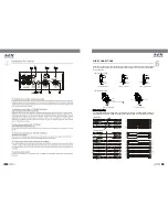
Rear Panel

This connection is where you connect the supplied external AC power supply to provide AC 
power to the mixer. Connect the external power supply to your mixer first, then plug the power 
supply into a suitable and properly rated AC outlet.


NOTE

: Make sure you use the correct external power supply cable of providing 18.5 VACx2 at

milliamps.

28- POWER IN 

28

MX.12 USB

29

POWER

Summary of Contents for MX series

Page 1: ...USER S MANUAL USER S MANUAL MX SERIES MX SERIES MIXER TAPE USB TO MIX NF03483 1 0 ...

Page 2: ...d Before turning the unit ON make sure that it is connected to Ground This is to prevent the risk of electric shock Never cut internal or external Ground wires Likewise never remove Ground wiring from the Protective Ground Terminal Operating Conditions Always install in accordance with the manufacturer s instructions To avoid the risk of electric shock and damage do not subject this product to any...

Page 3: ...TABLE OF CONTENTS 1 INTRODUCTION 1 2 FEATURES 1 4 CONTROL ELEMENTS 3 6 WIRE CONNECTIONS 9 3 USEFUL DATA 1 5 INSTALLATION TIPS 8 7 BLOCK DIAGRAM 10 8 TECHNICAL SPECIFICATION 14 9 GUARANTEE 15 ...

Page 4: ... right choice in purchasing the TOPP PRO MUSIC GEAR 1 mono inputs with gold plated XLR and Balanced TRS jack 2 stereo inputs with Balanced TRS jack 2 band EQ on all mono channels 2 Track IN OUT Balanced XLR TRS jack output MX 5 2 mono inputs 4 for MX 12 USB with gold plated XLR and Balanced TRS jack 4 2 for MX 6 USB stereo inputs with Balanced TRS jack GAIN control and 48V phantom power for mono i...

Page 5: ... Direct Box Guitar Digital Audio Interface Digital Audio Workstation Headphones Microphones Drum Machine Active Studio Monitors Small Club Gig Headphones Microphones 1 and 2 Mono in Stereo out Reverb Active Speakers CD Player DAT DAT Recorder Drum Machine Keyboard ...

Page 6: ...ynthesizers keyboards drum machines or effect devices NOTE Never try to connect a line level signal to the XLR MIC input when the phantom power is engaged doing this you may seriously damage your equipment They are organized in stereo pair and provided with 1 4 TRS sockets It is used to connect the stereo device plug both the left input and the right input Using the left input if connect a mono in...

Page 7: ...USB or stereo channel MX 10USB MX 12USB and be added to the main mix 7 8 9 9 10 10 11 11 12 12 12 LEVEL This control will adjust the overall level of this channel If you set the LEVEL control in max it s usually a sign that your GAIN is set too low If set the LEVEL control in min your GAIN may be too high 10 PAN BAL Abbreviation of PANORAMA control for mono channels for the stereo channels always ...

Page 8: ...le from these AUX SEND outputs 16 TAPE TO CTRL RM PHONES Switch TAPE TO PHONES on MX 5 Switch is used to select the signal source for the CONTROL ROOM outputs PHONES and METERS Release this switch they all receive the main mix signal tapped after the MAIN MIX control Engage this switch they all receive the CD TAPE Input signal Turn down the CTRL ROOM PHONES control just PHONES on the MX 5 before e...

Page 9: ...ernal device such as effects equipment Each channel has an AUX SEND control knob that adjusts h ow much of that channel s signal appear at each of the output This output is affected by the channe l LEVEL but not MAIN MIX control This jack is used to send out the mix signal to a pair of headphones and the signal is the same as the CTRL RM OUTS outputs The level is controlled by the CTRL ROOM PHONES...

Page 10: ...hat you do not use hubs and other extenders that often cause glitches and other problems The USB port sends the MAIN MIX left and right signals to the computer The USB port receives a stereo audio stream from the computer and assigns it to the 2 TRACK INPUT left and right channels of your mixer MX 6USB 10USB 12USB MX 6USB 10USB 12USB MX 6USB 10 USB 12USB Note if a device is connected to the 2 TRAC...

Page 11: ...ve Tip Sleeve Cente r Cente r Centre Screen Screen Screen 1 2 3 Tip Ring Sleeve 1 2 3 1 2 3 Tip Ring Sleeve 1 2 3 Tip Sleeve 1 2 3 TIP SLEEVE TIP SLEEVE TIP RING SLEEVE TIP RING SLEEVE 1 2 3 2 1 3 2 1 3 TIP RING SLEEVE TIP SLEEVE 1 2 3 1 2 3 SLEEVE TIP SLEEVE RINGTIP For these applications the unit provides 1 4 TRS and XLR connectors to easily interface with most professional audio devices Follow ...

Page 12: ...BLOCK DIAGRAM MX 5 7 8 9 9 10 10 11 11 12 12 ...

Page 13: ...BLOCK DIAGRAM ...

Page 14: ...TAPE USB TO MIX TAPE USB TO MIX DAT BLOCK DIAGRAM ...

Page 15: ...BLOCK DIAGRAM ...

Page 16: ... dBu Input Impedance 2 6 k balanced Mic Input Line Input 20 k balanced Stereo Aux Returns 20 k balanced CD Tape In 24 k unbalanced Output Impedance Main 240 balanced 120 unbalanced Ctrl Room Aux Sends 120 Tape Output 1 k Phones Output 25 VU Meters Main Left and Right 4 segment Clip 18 6 0 20 0 LED 0 dBu AC Power Requirements External Power Supply Ourput 18 5 VAC 2 150 mA 3 pin AC power connection ...

Page 17: ...nection of the equipment to other equipment different from the specified ones in the manual of use or by bad connection to these last ones Damages caused by electrical storms blows and or incorrect transport Damages caused by excesses or falls of tension in the network or by connection to networks with a tension different from the required one by the unit Damages caused by the presence of sand aci...

Page 18: ......

Reviews: