1
EC DECLARATION OF CONFORMITY
2
TECHNICAL DATA
MODEL
VOLTAGE SUPPLY
POWER
PROTECTION CLASS
OPERATING TEMPERATURE
EB1
24 V
5 W
IPX0
-5°C ÷ +50°C
The package contains:
1 EB1 electric lock;
1 fastening bolt;
1 connection cable L = 5m;
2 knob-based manual release kits
(Fig. 5)
;
1 wire-based release kit L = 1.5m
(Fig.6)
;
1 label for the optional remote control
(Fig.10);
1 instruction manual.
3
LIST OF COMPONENTS
4
TYPE OF USE
This device is designed to block the opening of slide-
away doors for interiors that are automated by Topp V1
and V1E actuators.
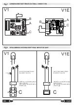
Minimum dimensions for installation
(see fig. 1-2).
The device is also equipped with an emergency release
(wire-based manual release), included in the box.
In order to use the EB1 in public spaces, the
wire-based manual release kit must be
installed at a height that can also be accessed
by disabled people and those with limited
movement.
This device is EC certified in that it forms part of the
accessories for the V1 and V1E actuators (See
paragraph 6 of the associated instruction manual for
installation and use).
5
INSTALLATION
INSTALLATION PRECAUTIONS:
After having checked
that installation is possible
(par. 4)
, select the type of
emergency release to be used (manual release kit or
wire-based release kit).
One release kit should be installed on the side
of the automation system and one should be
installed on the opposite side in order to
guarantee safe access from both directions.
In order to use the EB1 in public spaces, the wire-
based manual release kit must be installed at a height
that can also be accessed by disabled people and
those with limited movement.
Before installing the EB1, prepare the passage of the
connection cable and the passage of the wire-based
release kit where applicable. If necessary request the
services of a professional for installation.
INSTALLING THE ELECTRIC LOCK (Fig.3)
Install the EB1 as follows:
In the event of installation on Doortech doors, first
replace the anchoring bracket with the dedicated bracket
(to be ordered as an accessory)
(fig.4).
a-b
: Lift the attachment bracket and insert it into the
sliding trolley for the door;
c
: Slide the EB1 along the track until it meets the door
trolley;
d-e
: Close the door. The EB1 will be pulled into the
correct installation position;
f
: Open the door and secure the EB1 using the bolt
provided, without moving it from the position it reached.
WARNING: Take care not to use excessive
force as tightening the bolt too much may
damage the device.
INSTALLING THE MANUAL RELEASE KIT (Fig.5):
Install the manual emergency release kit as follows:
After having checked that installation is possible, find the
exact position and drill a hole in the door jamb using a
10mm drill bit. Cut the shafts to the defined length and
insert them into the EB1 as shown. Apply the knobs
provided.
TOOLS NECESSARY:
1 drill with 10mm drill bit;
1 wire stripper;
1 pair of clippers or hacksaw;
1 hacksaw for plastic (for manual release kit);
1 cross-tip screwdriver;
1 pencil.
6
EN
EB1


