background image

4.6

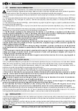
LIST OF MESSAGES AND ALARMS

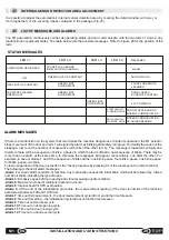
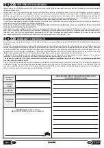
STATUS MESSAGES 

LED L1

LED L2

MESSAGES

ALTERNATING RED /GREEN

ALARM

GREEN LIGHT ON CONSTANT

RED LIGHT ON CONSTANT

CONSTANT FLASHING 
GREEN LIGHT

OFF

DOOR WAITING

PAUSE FOR REMOTE 
LEARNING

DOOR LOCKED 
BY REMOTE CONTROL

1 BLINK PLUS X BLINKS 
IN RELATION TO ALARM NO.

LED L3

LED L4

GREEN LIGHT
ON CONSTANT

24 V POWER ON

SLOW YELLOW
FLASHING LIGHT

DOOR STOPPED AND NO 
MODBUS COMMUNICATION

RAPID YELLOW
FLASHING LIGHT

MODBUS COMMUNICATION
OR GUIDED READING 

4.5

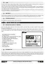
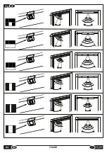
INTERNAL SENSOR DETECTION AREA ADJUSTMENT

It is possible to adjust the automation's internal sensor detection area by covering the detect window with one ( or 
more toghether ) of the covering masks contained in the package (Fig.27 ).

GREEN LIGHT
ON CONSTANT

GREEN LIGHT
ON CONSTANT

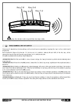
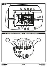
The M1 automation continuously verifies its operating status and can communicate, with the two leds L1 and L2, any 
malfunctions or particular states. The table below lists the possible messages. Refer to Figure 26 for the position of the 
leds.

29

EN

INSTALLATION AND USE INSTRUCTIONS

M1

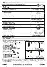
If there is a malfunction on the system that could make the machine dangerous or hinder its operation, the M1 actuator 
stops movement of the door and led L1 will signal the alarm by blinking alternately red/green. To identify the cause of the 
stoppage, just count the number of consecutive red blinks of the other led, L2. The message is repeated cyclically and 
therefore there will be a sequence of blinks, a pause in which the led is off and a new sequence of blinks. There may be 
more than one alarm at the same time. In this case the messages will appear consecutively, one after the other. For 
example, in case of alarms 1 and 4, the sequence of blinks will be: one blink, pause, four blinks, pause, one blink, pause, 
for blinks, pause, one blink,…
To restore operation of the door just perform the “reset” procedure by pressing S1 or the reset key on the remote control.
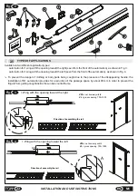
The following is the list of alarm messages:
-

Alarm 1

: Generic alarm condition of machine, any malfunction causes the initial blink, which will be followed by a fixed 

number of blinks indicating the type of alarm.
-

Alarm 3

: Excessive speed of door opening and closure causing unsafe condition.

-

Alarm 4

: Maximum number of collisions reached in closure.

-

Alarm 5

: Internal board of CPU overheated.

-

Alarm 6

: At the end of the initialization procedure, the measurement reading of the door is outside of the machine 

parameters (between 700 and 1,000mm).
-

Alarm 7

: time out for measurement – the door measurement cycle did not end in the time foreseen.

-

Alarm 8

: time out for setting – the initialization cycle did not end in the time foreseen.

-

Alarm 9

: Time out on door reset cycle.

-

Alarm 10

: Time out on door opening cycle.

-

Alarm 11

: Time out on door closing cycle.

-

Alarm 12

: Time out on door reversal cycle.

ALARM MESSAGES 

Summary of Contents for M1

Page 1: ...ISTRUZIONI PER L INSTALLAZIONE E L USO INSTALLATION AND USE INSTRUCTIONS IT EN pag 3 pag 18 AUTOMAZIONE MAGNETICA PER PORTE SCORREVOLI LINEARI AD UNA ANTA MAGNETIC AUTOMATION FOR SLIDING LINEAR DOORS WITH ONE WING BREVETTATO PATENTED ...

Page 2: ...2 ISTRUZIONI PER L INSTALLAZIONE E L USO IT M1 ...

Page 3: ...parazione attuatore pag 09 3 5 Montaggio dell attuatore sull anta pag 09 3 6 Montaggio e collegamento del sensore a microonde o infrarossi esterni accessorio pag 09 3 7 Rischi residui pag 10 4 USO E FUNZIONAMENTO 4 1 Descrizione tecnica pag 10 4 2 Procedura regolazione peso tempo apertura inizializzazione e reset pag 11 4 3 Programmazione e utilizzo del radiocomando a 433 Mhz accessorio pag 12 4 4...

Page 4: ...ossa elettrica Evitare i movimenti di componenti con magneti permanenti rispetto ai materiali elettricamente conduttivi e viceversa I campi magnetici possono provocare la perdita di dati nei supporti magnetici o elettronici Non portare sulla persona supporti magnetici o elettronici 1 1 AVVERTENZE GENERALI 1 3 INSTALLATORE 1 2 NORME GENERALI DI SICUREZZA Qualunque manomissione o sostituzione non au...

Page 5: ... l automazione in condizioni normali e di effettuare semplici operazioni di avviamento o ripristino dell automazione in seguito ad un eventuale sosta forzata attraverso l uso dei dispositivi preposti L utente non deve eseguire operazioni riservate ai manutentori o ai tecnici specializzati In caso di guasto o di malfunzionamento della porta l utente deve pertanto limitarsi a disinserire l alimentaz...

Page 6: ...zione ed è obbligatorio richiedere l assistenza tecnica del rivenditore o del costruttore 2 3 DATI TECNICI NelleTab 1 sono riportati i dati tecnici che caratterizzano l automazione M1 TENSIONE DI ALIMENTAZIONE FORZA MASSIMA DI SPINTA CLASSE DI ISOLAMENTO TEMPERATURA DI FUNZIONAMENTO NUMERO DI ANTE Utilizzo continuo 1 ANTA MODELLO Tab 1 USCITA TENSIONE PERIFERICHE POTENZA ASSORBITA ASSORBIMENTO VEL...

Page 7: ...to causato dalla presenza della maniglia a scomparsa l installazione dell automazione M1 prevede una riduzione del vano passaggio di circa 80 mm in modo da impedire probabili trascinamenti delle dita all interno del controtelaio a scomparsa 7 IT ISTRUZIONI PER L INSTALLAZIONE E L USO M1 Fig 3 1 Anta con apertura verso destra VL VPA A 80 A VPA vano passaggio utile VL vano luce massimo 700 1000 Sens...

Page 8: ...montaggio dell attuatore Questa tipologia di automazione deve essere installata in ambienti dove la porta non venga usata o usata molto raramente da parte di persone disabili anziane fragili o con limitate capacità motorie Nel caso si voglia utilizzare l automazione M1 in luoghi dove la presenza di suddette persone sia frequente l automazione M1 deve essere associata ad altri dispositivi di sicure...

Page 9: ...o sia posizionata verso il basso 3 4 MONTAGGIO DELLA STAFFA SUPPORTO E PREPARAZIONE ATTUATORE Per montare il binario precedentemente assemblato procedere come descritto Figura 10 Applicare le dime di montaggio del binario come indicato in figura facendole scattare nella sede delle guide corsia binario e avendo cura di applicare quella apposita in testa La dima di testa è stata progettata per in bo...

Page 10: ...llegato alla rete domotica tramite Bus fino a 63 attuatori utilizzabili in un unica rete la possibilità di aggiornare il software tramite ingresso seriale su scheda di programmazione Nel caso in cui vi sia mancanza di tensione esiste una funzione di ripristino automatico della porta L automazione M1 è stata progettata in modo tale che la porta in buone condizioni possa essere movimentata con una f...

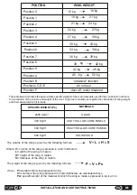
Page 11: ...ntare Una regolazione errata del selettore può provocare un malfunzionamento dell automazione oltre ad un comportamento pericoloso della porta stessa 4 2 PROCEDURA DI REGOLAZIONE PESO TEMPO APERTURA INIZIALIZZAZIONE E RESET Di seguito viene riportata la tabella dove sono indicati i pesi specifici indicativi dei principali materiali utilizzati per la costruzioni delle porte e le formule per il calc...

Page 12: ... L avvio di tale procedura può essere fatto mediante la pressione per 2 secondi del tasto S1 o premendo il tasto 7 Reset del telecomando A seguito del comando la porta aprirà a velocità molto bassa per poi richiudersi a velocità impostata Una volta richiusa si porrà in stato di attesa comandi ripristinando il funzionamento normale Il tempo di sosta a porta aperta durante il ciclo di reset è molto ...

Page 13: ...so in cui la porta abbia un peso medio alto può verificarsi la possibilità che la porta non completi il ciclo di apertura quindi sarà opportuno riportarlo in posizione di OFF DIP SWITCH N 7 Permette di selezionare la porta come principale o secondaria in caso di funzionamento in tandem due attuatori collegati Se portato in posizione di ON la porta ha un funzionamento principale da utilizzare per p...

Page 14: ...cutivi rossi dell altro led L2 Il messaggio viene rappresentato ciclicamente e quindi ci sarà la sequenza di lampeggi un periodo di pausa in cui il led è spento e una nuova sequenza di lampeggi Potrebbe succedere che avvengano più allarmi contemporaneamente in questo caso i messaggi appariranno consecutivi uno all altro Per esempio se gli allarmi saranno il n 1 e il n 4 la sequenza dei lampeggi sa...

Page 15: ...aTOPPSpAnon sono permessi 5 2 ACCESSORI E RICAMBI A RICHIESTA È vietato l impiego di ricambi ed accessori non originali che possono compromettere la sicurezza e l efficienza dell automazione e far decadere la garanzia I ricambi e gli accessori originali devono essere richiesti esclusivamente al rivenditore di fiducia o al fabbricante comunicando tipo modello numero di serie e anno di costruzione d...

Page 16: ... impatto Assicurarsi che non ci siano ostacoli nel vano passaggio Eventualmente pulire la riga ottica o chiamare l assistenza Durante il movimento della porta l attuatore produce un rumore anomalo di sfregamento Smontare l attuatore dalla porta e rimuovere con uno straccio la polvere ed eventuali detriti sia dal binario che dal rotore Allarme 1 Eseguire procedura di reset e se necessario procedura...

Page 17: ... 2 103 EN 16005 EN 61000 6 2 EN 61000 6 3 La macchina soddisfa inoltre i requisiti richiesti dalle seguenti Direttive Europee LVD 2006 95 CE EMC 2004 108 CE R TTE 1999 5 CE La persona incaricata a custodire il fascicolo tecnico è Ilenia Dal Bianco Topp spa via Galvani 59 36066 Sandrigo VI ITALIA Data Sandrigo 01 09 2014 Matteo Cavalcante TOPP S p A via L Galvani 59 36066 Sandrigo VI ITALIA IT DICH...

Page 18: ...or on the wing page 24 3 6 Assembling and connecting the microwave and infrared sensor optional page 24 3 7 Residual hazards page 25 4 USE AND OPERATION 4 1 Technical description page 25 4 2 Procedure for adjustment of the weight opening time initialization and reset page 25 4 3 Programming and use of the 433 MHz radio control device optional page 27 4 4 Programming the dip switches page 28 4 5 In...

Page 19: ...e versa Magnetic fields can cause the loss of data in magnetic and electronic devices Do not carry any magnetic or electronic devices on your person 1 1 GENERAL RACCOMENDATIONS Special maintenance different from the maintenance foreseen in this manual of the automation must be performed exclusively by qualified technical personnel in possession of the professional requisites foreseen by the legisl...

Page 20: ... 1 4 The user must be able to operate the automation under normal conditions and perform simple operations of startup or resumption of use of the automation after a forced interruption with the devices foreseen The user must not perform operations restricted to maintenance personnel or specialized experts In case of breakdown or malfunction of the door the user may only disconnect the power supply...

Page 21: ...facturer 2 3 TECHNICAL DATA Tab 1 lists the technical data that characterize the M1 automation POWER SUPPLY MAXIMUM THRUST FORCE PROTECTION AGAINST ELECTRIC SHOCKS WORKING TEMPERATURE NUMBER OF DOOR PANELS Continuous 1 PANEL MODEL Tab 1 PERIPHERAL POWER OUTPUT POWER ABSORBED ABSORPTION OPENING CLOSING SPEED WEIGHT CONTROL DOOR DOOR OPEN WAITING TIME TYPE OF USE MAXIMUM CAPACITY SIZE OF OPENING 700...

Page 22: ...ce of the disappearing handle the installation of M1 automation provides for a reduction of the passage space by about 80 mm in order to prevent the fingers from getting caught inside the sunken counterframe 22 INSTALLATION AND USE INSTRUCTIONS EN M1 Fig 3 VL VPA A 80 A Direction of assembling the rail Fig 4 VPA VL A A 80 Direction of assembly the rail VPA net doorway width VL gross opening 700 10...

Page 23: ...utomation should be installed at sites where the door is never or rarely used by disabled persons the elderly fragile individuals or those with limited motor capabilities Children must not be allowed to play and or stand in the radius of action of the door If you wish to use the M1 automation is places where the presence of such individuals is frequent the Topp M1 automation must be associated wit...

Page 24: ... care to apply the appropriate one at the head The head template has been designed for a depth of the jamb 10mm For deeper measurements do not use the template but regulate the position of the rail so that it does not interfere with door closure Figure 11 Open the door by about 50 mm and insert the rail in the space between the wing and the sheet metal case position the installation templates so t...

Page 25: ...shed or pulled slightly ultraslow nighttime function can be selected with the remote control which reduces the noise the possibility of connection of two wing doors using the communication protocol the possibility of connection to the domotic network via Bus up to 63 actuators usable in a single network the possibility of updating the software through the serial input on the programming board In c...

Page 26: ... meters Where P weight of the wing expressed in Kg V volume of the wing expressed in cubic millimeters as calculated above Ps specific weight of the material of which the wing is made expressed in kg cu mm V L x H x S P V x Ps The volume of the wing is given by the following formula The weight of the wing is given by the following formula 26 INSTALLATION AND USE INSTRUCTIONS EN M1 POSITION WING WE...

Page 27: ...omation is ready to use If it should be necessary to change the VPA or other the procedure has to be repeated After initialization the standing by for open command status is confirmed by LED S2 on with fixed green light This status remains unchanged until the door is commanded to open and returns at the end of the open close cycle If during the initialization procedure the door does not reach the ...

Page 28: ...or as main or secondary in case of tandem operation In the ON position the door functions as the main door and in the OFF position the door has secondary function and stands by for commands from a main door DIP SWITCHES no 6 5 4 3 2 1 These are used to set the door address In case of a single door all the dip switches must be set to OFF In case of tandem operation the setting of the dip switches m...

Page 29: ...page just count the number of consecutive red blinks of the other led L2 The message is repeated cyclically and therefore there will be a sequence of blinks a pause in which the led is off and a new sequence of blinks There may be more than one alarm at the same time In this case the messages will appear consecutively one after the other For example in case of alarms 1 and 4 the sequence of blinks...

Page 30: ...ARE PARTS AND ACCESSORIES AVAILABLE ON REQUEST Always use original spare parts and accessories to ensure the safety and efficient operation of the automation and avoid invalidating the warranty Original spare parts and accessories must be ordered exclusively from the dealer or manufacturer communicating the type model serial number and year of construction of the automation The following accessori...

Page 31: ...ourth signals the collision alarm Make sure there are no obstacles in the passage space If necessary clean the optical line or call Customer Service During the door movement the actuator produces an unusual friction noise Remove the actuator from the door and clean with a cloth possible dust and dross from track and rotor Alarm 1 Perform the reset procedure and if necessary repeat initialization A...

Page 32: ...335 1 EN 60335 2 103 EN 16005 EN 61000 6 2 EN 61000 6 3 The machine also complies with the requisites of the following European Directives LVD 2006 95 CE EMC 2004 108 CE R TTE 1999 5 CE The custodian of the technical file is Ilenia Dal Bianco Topp spa via Galvani 59 36066 Sandrigo VI ITALY Date Sandrigo 03 09 2014 Matteo Cavalcante TOPP S p A via L Galvani 59 36066 Sandrigo VI ITALY IT EC CONFORMI...

Page 33: ... 1 11 800 1 11 850 1 12 900 1 13 950 1 13 1000 33 M1 FIGURE Fig B B guida collegamento rotore binario rotor rail connecting guide 8 Fig 9 VL 700 730 750 800 800 880 880 850 900 950 950 1000 1000 1000 A A A Fig 7 A guida tacchettata notched guide A A ...

Page 34: ... 34 FIGURE M1 Fig 11 5 0 Fig 10 ...

Page 35: ... FIGURE Fig 14 C Senso di montaggio direction of assembly C C VL 20mm IT Per regolare la lunghezza dell attuatore accompagnare all interno il cavo di alimentazione EN To regulate the actuator length guide the cable into the actuator itself 1 7Nm ...

Page 36: ...Fig 15 Fig 17 1 2 34 5 Fig 16 Fig 18 36 FIGURE M1 Coppia di serraggio 1 7Nm Force equal to 1 7Nm A ...

Page 37: ...Fig 19 75 10 Fig 20 37 M1 FIGURE ...

Page 38: ... M1 FIGURE 38 Fig 21 Fig 22 ...

Page 39: ...URRO 24V BLUE 24V BIANCO CONTACT WHITE CONTACT GIALLO GND YELLOW GND 5V Rif E fig 26 APERTURA A SINISTRA OPENING TOWARD THE LEFT APERTURA A DESTRA OPENING TOWARD THE RIGHT AZZURRO BLUE 12 24v GIALLO YELLOW GND BIANCO WHITE CONTACT NO Ws2 Is4 BIANCO WHITE CONTACT NO GIALLO YELLOW GND AZZURRO BLUE 5v Fig 23 ...

Page 40: ... M1 FIGURE 40 Fig 70mm 24 Fig 25 TOPP M1 TOPP M1 ...

Page 41: ... 41 M1 FIGURE GND CONTACT 5V 24V GND 5V 24V CONTACT Rif per collegamento pulsanti esterni Ref for connecting external buttons D E Fig 26 C L1 L2 A D E S1 S2 B F 3 2 1 L3 L4 ...

Page 42: ... M1 FIGURE 42 Fig 27 ...

Page 43: ...P Spa da qualsivoglia responsabilità in ordine agli usi impropri alla mancata osservanza delle norme di sicurezza delle specifiche tecniche e delle istruzioni per l installazione e l uso IT CERTIFICATO DI GARANZIA 8 Warranty for faults or defects according to art 1490 of the Civil Code covers products and single parts of products for 24 months after the shipment from the factory Warranty for the g...

Page 44: ...TOPP SPA Società a socio unico soggetta a direzione e coordinamento di 2 Plus 3 Holding S p a Via Galvani 59 36066 Sandrigo VI Italia Tel 39 0444 656700 Fax 39 0444 656701 ...

Reviews: