IT
GENERAL REMARKS
2
2.1
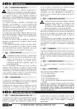
GENERAL INSTRUCTIONS
Installation, startup and maintenance of the power
unit must be done exclusively by specialized
personnel in possession of the technical and
professional requisites foreseen by the legislation in
force in the country of installation.
The specialized electrician must be able to install the power
unit, start it and make in work in "maintenance" mode; he
must be able to perform all repairs of an electrical and
mechanical nature and perform any adjustments and
maintenance and must be able to operate the device with the
The user of the device must comply with the instructions in
this manual.
The user must be able to operate the control unit under
normal conditions, using the controls provided. The user
must also be able to operate the control unit during
maintenance and perform simple operations of routine
For service, contact your local distributor or the
manufacturer.
The warranty on the device is invalidated if it is used in ways
that do not comply with the instructions and regulations
indicated in this manual and if parts, accessories,
replacements and control systems other than original ones
are used (see
pag.23
).
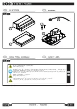
Every standard package (
Fig.1
) of the product contains:
1
. N.1 Lower housing
2
. N.1 Upper housing
3
. N.1 RR circuit boar
4
. N° 2 self-tapping screws d2,9x13
5.
N °1special cable for manual (deviator) key connection.
Make sure the package contains all the parts described
above and that they have not been damaged in shipment. If
you find anything wrong do not install the shipment. If you find
anything wrong do not install the power unit. Request
technical assistance from your local distributor or the
manufacturer.
The power unit is designed and must be used
exclusively to power and drive "ORIGINAL TOPP"
motors for windows and doors, and any other type of
use is strictly forbidden unless authorized by TOPP.
&
The power unit must be kept on the premises in a suitable
position depending on the distance of the motors to drive in
respect of the safety conditions foreseen in the country of
use.
&
Do not install the power unit outside the premises subject
to atmospheric agents.
&
Do not use the power unit in premises with a potentially
explosive atmosphere.
2.2
INSTALLER
2.3
THE USER
2.4
FIELD OF APPLICATION
2.5
WARRANTY
2.6
TECHNICAL ASSISTANCE
2.7
PACKING
Before installing the device the installer must read
and understand all parts of this manual.
&
This manual is an integral part of the device unit and must
be kept by the installer, with all the enclosed documentation,
for future reference.
&
This manual provides all instructions necessary to ensure
correct installation and maintenance of the device: TOPP srl
is not liable for any damage to persons, animals and property
caused by failure to follow these instructions.
&
This manual was written by TOPP srl, which holds the
copyright. No part of this manual may be reproduced or
published without the manufacturer's written authorization.
&
TOPP srl reserves the right to amend or improve the
manual and the products described therein at any time
without notice.
&
The data contained in this manual were written and
checked with the maximum care; TOPP srl is not liable for
possible errors due to omissions or printing errors, or errors in
transcription.
maintenance (cleaning).
The user must not perform operations restricted to
maintenance personnel or specialized experts. The
manufacturer is not liable for damages deriving from failure to
comply with this prohibition.
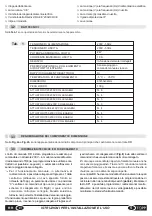
% Symbol of double electric insulation
% Symbol of “WEEE” 2002/96/CE
% Type and model
% Voltage (V) and frequency (Hz) of electrical power
% Output voltage (V) and output frequency (Hz)
% Maximum output current (A)
% IP protection degree
% Version
The "CE" marking certifies the conformity of the TF33 with
the essential requisites of health and safety contemplated by
the European product directives. This marking consists of an
adhesive plate in polyester, silkscreen printed in black, that is
applied to the outside of the device. The plate indicates
legibly and indelibly the following data:
% Manufacturer’s logo
% “CE” seal
IT
3
3.1
RATING PLATE AND “CE” MARKING
12
EN
RR
INSTALLATION AND USE INSTRUCTIONS
TECHNICAL DESCRIPTION
Summary of Contents for RR
Page 23: ......


