Before wiring the motors to the power unit make sure
they have been correctly installed on the windows in
accordance with the relative "INSTRUCTIONS FOR
INSTALLATION AND USE".
&
Electrical connection of the power unit must be made
exclusively by experienced, qualified personnel in
possession of the professional technical requisites foreseen
by the legislation in force in the country of installation, who
5.4
ELECTRICAL CONNECTION
must issue the client a declaration of conformity of the
connection and/or installation performed.
&
Before performing electrical connection of the
actuators to the power unit, disconnect power at the mains.
&
The electrical power mains to which the power unit is
connected must possess the requisites foreseen by the
legislation in force in the country of installation, and comply
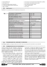
the technical data listed in
Tab.1
and on the rating plate
with the "CE" seal (
par.3.1
).
&
The cross section of the wires of the electrical power
line must be appropriate for the electrical power absorbed.
&
Any type of electrical material used for connection must
be suitable for the use, bearing the "CE" seal and must
comply with the requisites foreseen by the legislation in
force in the country of installation.
&
If the window is accessible or is installed at a height of
less than 2.5m from the ground, and could be controlled by
an untrained user or remote control, equip the system with
an emergency stop that acts automatically to prevent the
risk of crushing or dragging the parts of the body inserted
between the mobile part and the fixed part of the window.
&
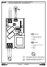
Always use wires with double insulation to make the
connections shown in the wiring diagrams (
Fig.8
-
Fig.9
).
&
To ensure effective separation of the electrical power
system, it is essential to install, upstream of the device, an
instant bipolar circuit breaker (switch) of the approved type.
It is also necessary to install a main bipolar circuit breaker
upstream of the control line, with a contact opening of at
least 3 mm.
&
It is strictly forbidden to install the power unit outside the
building where it may be subject to atmospheric agents,
and to use it in places with a potentially explosive
atmosphere.
IT
USE AND OPERATION
6
6.1
GENERAL INSTRUCTIONS
6.2
PROGRAMMING THE DIP-SWITCHES
Use of the power unit must be assigned exclusively to
users who comply with the instructions contained in
the manual and/or related TOPP device manuals
(such as window actuators).
&
The user shall constantly verify the functional efficiency in
time and nominal performance of the actuators, the windows
where they are installed and the electrical system and, when
necessary, shall have qualified technical personnel perform
actions of routine and special maintenance to guarantee
proper working conditions and respect of the safety
regulations.
&
The user, before using the motors connected to the power
unit in manual mode, shall ascertain that near and/or under
the window there are no persons, animals or objects whose
safety could be accidentally endangered, and that the
position of the person using the controls is safe and
guarantees visual control of the window's movements.
&
If the building in which the power unit is installed is left
unguarded, the automated windows must be closed to
The programming of the dip-switch is of primary importance
to ensure the correct functionality of the control unit. Each
dip-switch can be set ON or OFF.
Ÿ
DIP-SWITCH No.1: Rain sensor or manual control via
cable
% With dip-switch No.1
OFF
, input J1 must be used for
connection of a deviator key with central “0” position and
“deadman” type switch to open and close the actuator
.
% With dip-switch No.1
ON
, however, connector J1 can
be used as the input for the rain sensor TOPP RDC/12V.
Ÿ
DIP-SWITCH No.2: “Automatic” or “Deadman” mode
% With dip-switch No.2
OFF
the control unit functions in
“DEADMAN” mode.
% With dip-switch No.2
ON
the control unit functions in
“AUTOMATIC” mode and the manual control from the
15
EN
RR
sensor. To trip the sensor, it is sufficient to touch the sensitive
part with a finger after giving the actuator the open order
(there is no danger of electrocution as the device is protected
and operates at low voltage).
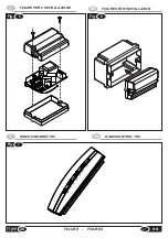
To install the control unit (
Fig.5
and
Fig.6
) proceed as follows:
% Open the top casing on the control unit;
% make the electrical connections as shown in the wiring
diagrams in
Fig.8
or
Fig.9
and described in
par.5.4
;
@
If you choose to use connector J1 as input for the rain
sensor, see the diagram in
Fig.8
.
@
If you choose to use connector J1 as input for a deviator
key with central “0” position and “deadman” type switch,
see the wiring diagram in
Fig.9
. In this case, the deviator
key must be connected to the RR with a special cable
supplied on request by TOPP
.
% close the RR with the screws AF d2.9x13 taking care not
to damage the radio antenna;
% place the control unit in a built-in case mod.503 or
enclosed in a place where it is not exposed to atmospheric
agents and not accessible to the user (
Fig.6
)
.
5.3
INSTALLATION OF THE RR
prevent any malfunctions caused by problems on the power
mains or sensors.
INSTALLATION AND USE INSTRUCTIONS
Summary of Contents for RR
Page 23: ......


